- D 0 ・ -
logo�Q0310�forGraphic
070509�Gdesign�ito
VBA20001-R.3720.A
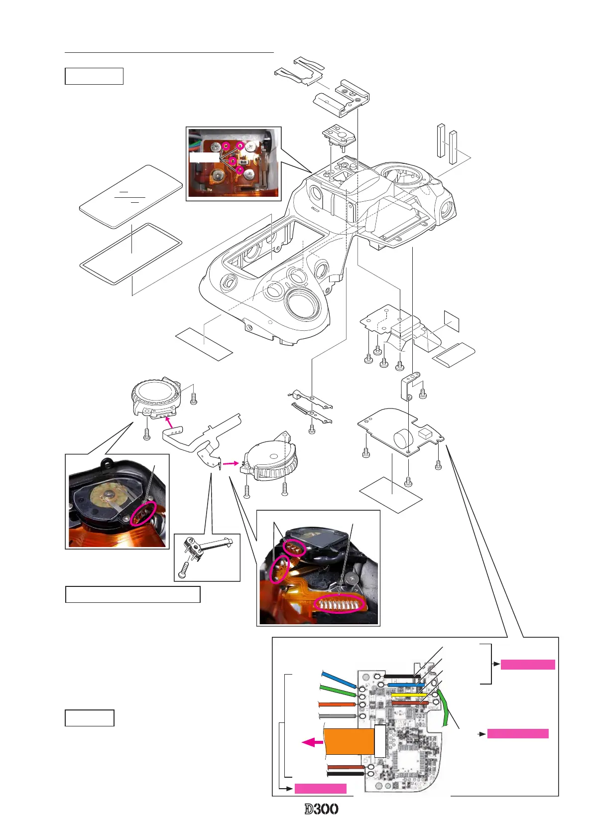
Command dial, Shoe base and other small parts
SB-PCB
・
Disconnect the FPC from the connector.
・
the wire of the synchro-terminal.
・
Take out the screws (#1511, #1535, and #1541),
and remove the SB-PCB.
#318
#316
Shoe base
・
Take out the four screws (#321).
・
Remove the four solders of the shoe base.
#B726
#1571×2
#B725
#1544×2
#1033
#958
#1541
#1511
#1535
#1565
#324
#323
#517
#1541
#708
#701
#702
#B317
#920
#972
#321×4
#948×2
#B735
#1605
※
SB-PCB soldering position
Green
Sync. terminal
Black
Blue
Yellow
Brown
Black
Brown
Blue
Green
Orange
Gray
DI base plate
FPC
Soldering bridge
Solder
Solder
Solder
Command dial/ Release-SW
・
Unsolder the release-SW (#B735), command
dial (#B726)(#B725), and remove the soldering
bridges, then remove the FPC (#1033).
・
Take out the two screws (#1571) and two screws
(#1544), and remove the command dial.
・
Take out the screw (#1605) and remove the
release-SW.
 Loading...