VBA20001-R.3720.A
- A 12 ・ -
logo�Q0310�forGraphic
070509�Gdesign�ito
<
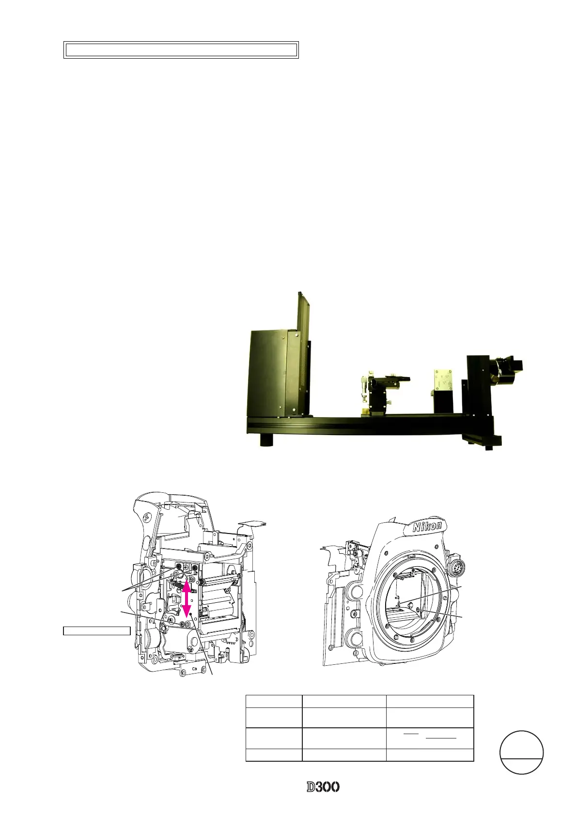
Device
>
1. For Main mirror adjustment
①
Mirror angle inspection tool
②
45° angle mirror tool
③
Hexagonal wrench (φ1.5mm
)
2. For sub-mirror adjustment
①
Mirror angle inspection tool
②
Hexagonal wrench (φ1.5mm
)
・
Main mirror 45° adjustment
Caution: Before and after the adjustment, check the accuracy by moving the main mirror up- and downwards a
few times.
①
Check for the right-left deviation
In case the result is out of standard, loose the two screws (#1523) and one screw (#1568), then make the
adjustment by moving the main mirror shaft PCB (#B10212).
②
Check for the up-down deviation.
In case the result is out of standard, make the adjustment by turning the eccentric pin.
・
Sub-mirror 59° adjustment
Caution: Before and after the adjustment, check the accuracy by moving the main mirror up- and downwards a
few times. Conrm if the two-pronged part of the sub-mirror rmly ts in the eccentric pin.
①
Check for the up-down deviation
In case the result is out of standard, make the adjustment by turning the sub-mirror eccentric pin.
Main mirror shaft base plate
#B10212
#1523×2
#1568
※
①
Mirror angle-inspection tool
Caution
:
Do NOT release the shutter.
Set the (supplied) tilted mirror with the main mirror being slightly lifted
so that the sub-mirror of D300 does not touch the (supplied) tilted
mirror of the inspection tool.
※
Procedure: Follow the operating instructions of the tool for main/sub mirror angle-inspection (J19132).
Main mirror
Sub-mirror
Left-right
deviation
±10’ -
Up-down
deviation
±5’ ±10’ -15±15’
Distortion
6’or less
6’or less
< Standard value >
Angle adjustment of Main mirror and sub-mirror
Apply after the
adjustment
Adhesive: Screwlock
Eccentric pin for the
sub-mirror
Eccentric pin for the
main mirror
Changed Page
△
×1 Feb.1st.2008
△(
Revision
)
 Loading...