VBA20001-R.3720.A
- A ・ -
logo�Q0310�forGraphic
070509�Gdesign�ito
7. Summary
The summary on each adjustment is as follows:
・When the DG-PCB is replaced, write the serial number.
・When the DG-PCB or image sensor holder unit is replaced, write the unique data.
image with the hand scanner. Write "D300_0001 ~ .csv" data in the DG-PCB.
※ The data will be added every two weeks (e.g. D300_0001.csv, D300_0002.csv, D300_0003.csv...), so
so that the difference between Gr and Gb output can fall in the standard range.
(2)Dark current adjustment
Take a picture of the blackout surface (against dark background) and adjust the shooting conditions in total
darkness. ※ When the adjustment is made, use eyepiece cap (or black cloth).
(3) Sensitivity adjustment
Camera is faced to
the adjustment is made by changing the ampgain so that G output can fall in the standard range. The gain
The actual adjustment of the gain value is made only under the condition of ISO200 and ISO1600, and the
medium sensitivity is calculated by the adjustment values of these 2 conditions.
For target output level, G output average of sensitivity reference value (ISO200) is used, which was
calculated by the reference body.
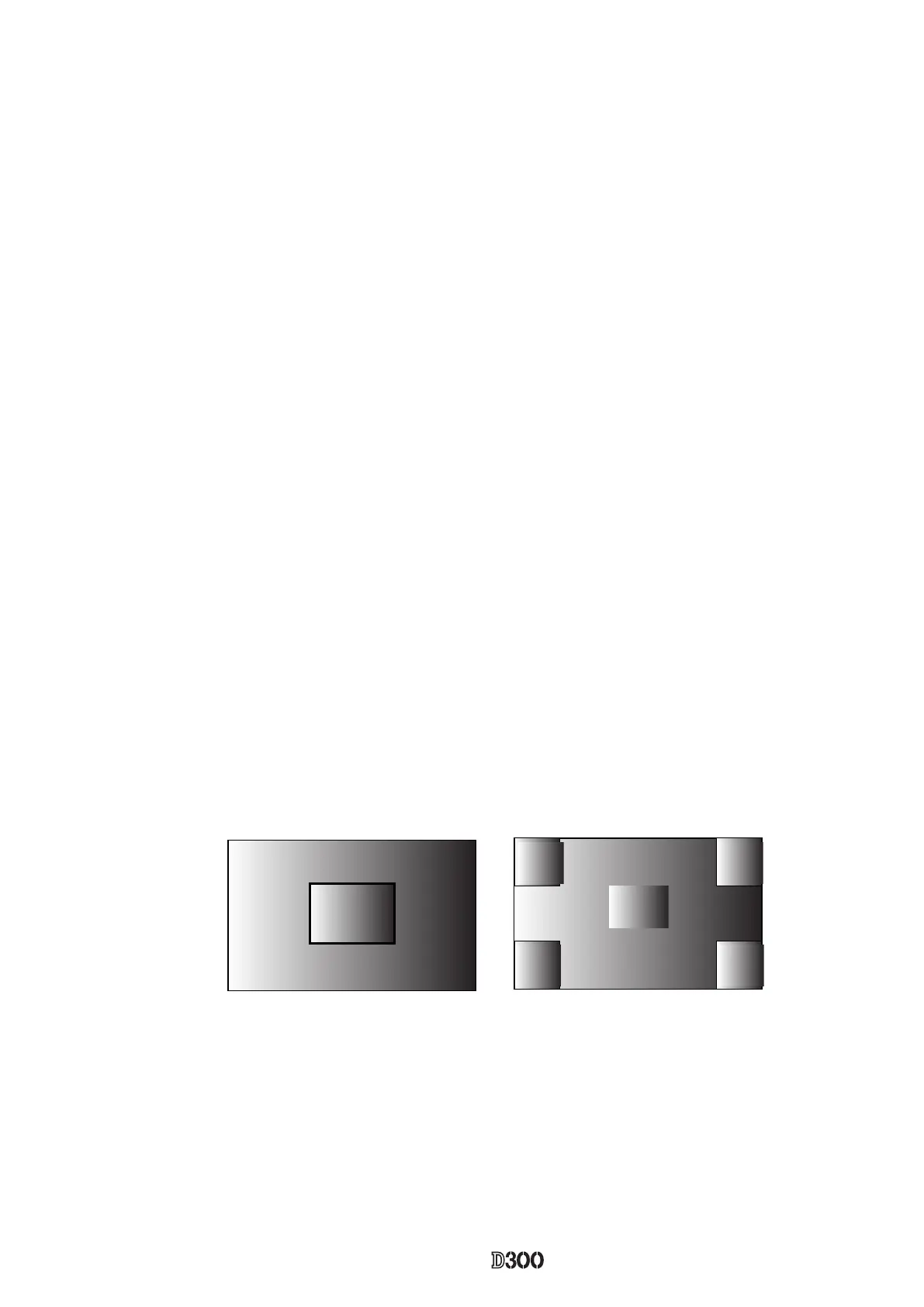
(4)Shading adjustment (5100K color viewer is shot by this camera, and adjustment is made.)
the adjustment of white balance distribution is made for 3 areas [Area ①
Area ② ③
Area ③ ]
(5)
being put between them, and the adjustment is made so that the difference in G output average between B-G
line and G-R line when the whole screen is divided in areas, can fall in the standard range.
(6)Sensitivity ratio adjustment
With the shutter tester of LV9, the adjustment is made so that the R/G, B/G output becomes the same as the
output ratio of the sensitivity ratio reference value that was calculated by the reference body. The adjustment
Area
②
Area
③
Area
③
Area
③
Area
③
Area
①
1416
 Loading...