Chapter 8 Functions and Operations of the Devices
129
11.2
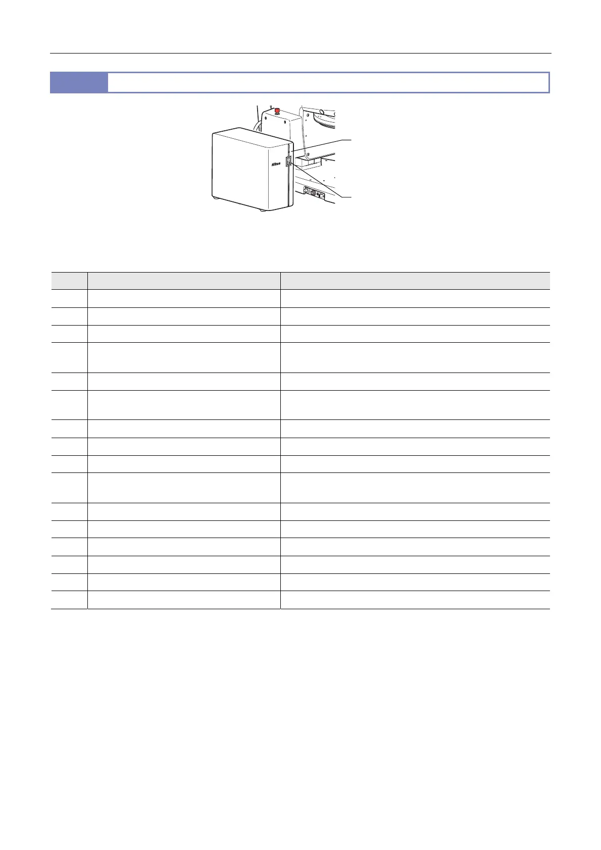
P2-CTLA Control Box
P2-CTLA Control Box
When electrically connected to the following devices, the P2-CTLA Control Box can perform motorized control of the devices,
detect the device states, and handle communications:
No. Device Operation
(1) SMZ25 Zooming body Motorized control of magnification
(2) SMZ18 Zooming body Detects the magnification.
(3) P2-MFU Motorized Focus Unit Motorized control of focus
(4) P2-DBL LED Diascopic Illumination Base Turns On/Off LED illumination, controls illumination, and monitors
the light intensity.
(5) P2-RLY Relay Box Relays communications.
(6) P2-EFLM Motorized Epi Fluorescence
Attachment
Motorized control of turret rotation
(7) P2-EFLI Epi Fluorescence Attachment Detects the turret address on the optical path.
(8) P2-RNI2 Intelligent Nosepiece Detects the nosepiece address on the optical path.
(9) P2-RC Remote Controller Communications
(10) AZ-FSW Foot Switch Detects the switch states, moves the P2-MFU Motorized Focus Unit
vertically, and adjust the magnification of the SMZ25 Zooming Body.
(11) AZ-PCR Photo Release Detects the switch states and captures images.
(12) C-HGFIE HG Precentered Fiber Illuminator Switches the ND filter and opens/closes the shutter.
(13) C-HGFIE HG Precentered Fiber Illuminator Communications
(14-1) DS-L4 camera control unit plus DS camera Communications
(14-2) Personal computer plus DS camera Communications
(15) AC adapter 24 V power input
• The power supply for control provides power for the board in the control box and devices (1) to (11).
• Devices (1), (2), (6), (7), and (8) are connected through device (3) or (5).
• One type-B USB connector is equipped so that device (14-1) or (14-2) can be connected. Note that both devices cannot
be connected at the same time.
• To operate using a personal computer after connecting device (14-1), connect the USB cable from the personal computer
to device (14-1).
• Communications with device (9) are handled through serial communications, communications with device (13) are
handled through a RS232C connection, and communications with device (14-1) or (14-2) are handled through a USB
connection.
Power LED
Power switch
 Loading...