Chapter 3 Assembling
48
3.3
Assembly of Other Devices (Optional)
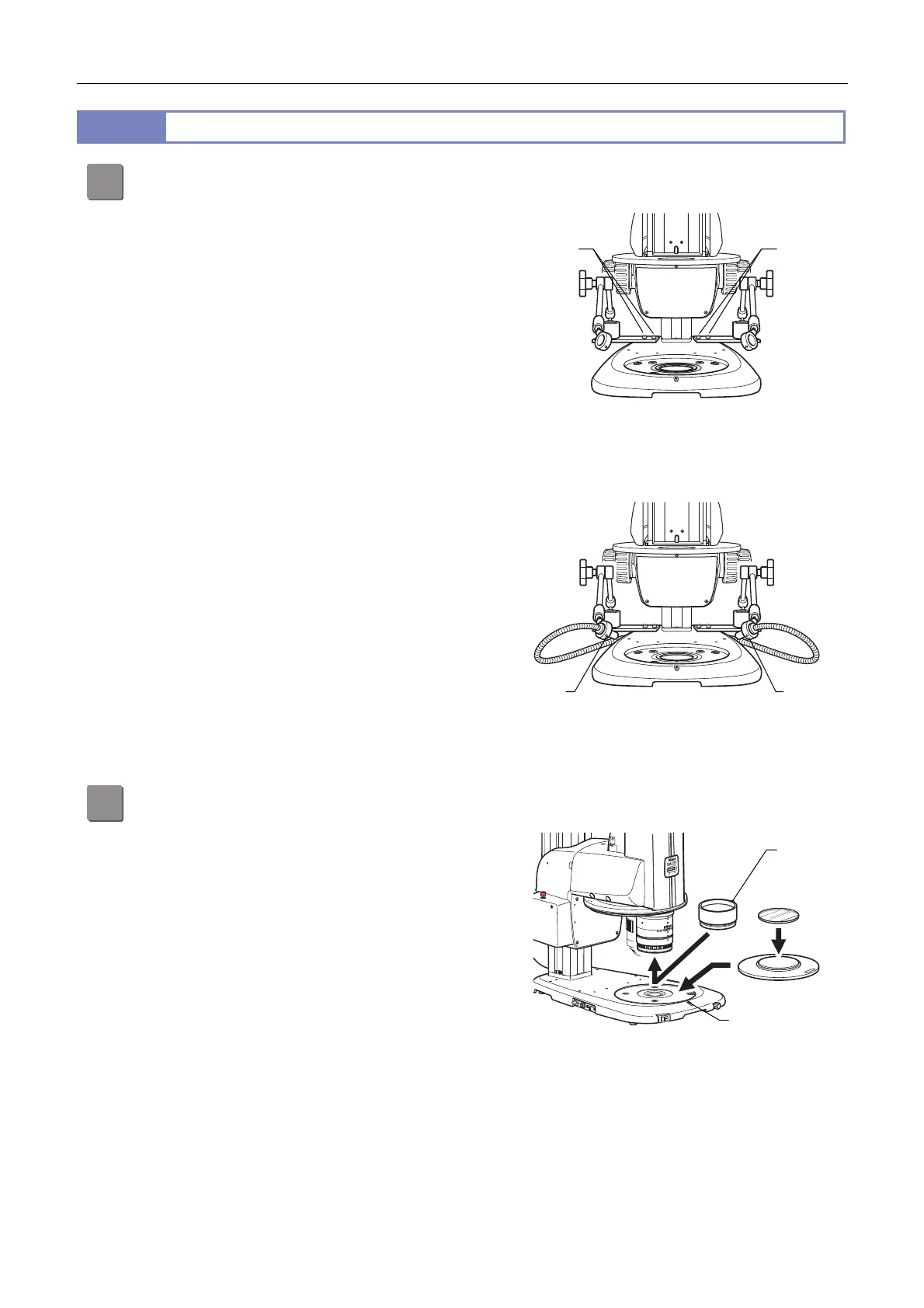
1
Attach a C-FDF Flexible Double Arm Fiber Illumination Unit.
The C-FDF can be attached to any types of bases and
stands.
(1) Attach a base of the C-FIDH Fiber Holder to the right
and left rear sides of the base. Two bolt holes are
located on each side.
Attaching the fiber holder by tightening the bolts
(2) Fit the flexible double arm fiber tip to the ring at the
arm end and tighten the M4 set screw for the fiber
using the hex driver (nominal designation: 2).
(3) Firmly insert the fiber source side connectors into
the C-FLED2 LED Light Source attachment holes.
Refer to the instruction manual supplied with the
light source for details.
Attaching the flexible double arm fiber
by tightening the screws
2
Attach a P2-POL Simple Polarizing Attachment.
The P2-POL can be attached to two kinds of bases
(P2-DBL and P2-DBF) and two kinds of stands (P-DSL32
and P-DSF32).
ttach a P2-SHR Plan Apo 0.5X or 1X objective.
(1) Loosen the M4 set screw for the stage plate on the
base or the stand using the hex driver (nominal
designation: 2) to detach the stage plate, and fit the
base plate of the polarizer into the diascopic
illumination base.
(2) Determine the orientation of the polarizer and
tighten the stage plate fixing screw.
(3) Place the stage glass (90 mm dia.) supplied with the
polarizer attachment on the polarizer.
(4) Loosen the fixing screw of the analyzer. Fit the
analyzer into the objective end until it reaches the
limit, and tighten the fixing screw.
Attaching the simple polarizing attachment
by tightening the screws
Fixing
bolts
Fixing
bolts
Fixing
screw
Fixing
screw
Fixing
screw
Fixing
screw
 Loading...