Chapter 8 Functions and Operations of the Devices
130
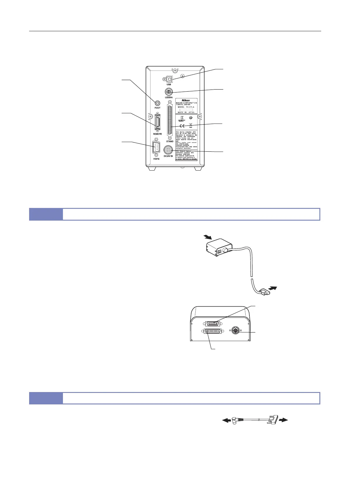
Connector names and connection destinations
The figure below shows the connectors on the rear of the control box and the connection destinations:
Rear of the P2-CTLA
Use the power cable specified in Chapter 5, “1 Performance Properties.”
11.3
P2-RLY Relay Box
When electrically connected to the following devises, the P2-RLY
Relay Box can relay signals for motorized control of the devices
and detect the device states:
(1) P2-CTLA Control Box
(2) P2-CTLB Control Box
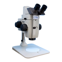
(3) SMZ25 Zooming Body
(4) SMZ18 Zooming Body
(5) P2-EFLM Motorized Epi Fluorescence Attachment
(6) P2-EFLI Epi Fluorescence Attachment
(7) P2-RNI2 Intelligent Nosepiece
• The drive signals of devices (3) and (5) are relayed through
device (1) or (2). For devices (4), (6), and (7), address
information signals are relayed.
ttach the relay box to the P2-FU Focus Unit or the P2-FMDN
Focus Mount. (See Chapter 3, "3.1 Assembling the EPI System
and DIA + EPI-FL System", step 5 "Attach a relay box." (P2-FU
Focus Unit system only" and Chapter 3, "3.2 Compact System
ssembly", step 4 "Attach a coaxial epi illuminator (in the
compact/epi-fl system))
P2-RLY Relay Box
11.4
P2-RLYC Relay Cable
For systems where the P2-RLY Relay Box has not been
connected, the P2-RLYC Relay Cable is used to connect the
SMZ18 Zooming Body to the RELAY connector of the P2-CTLB
Control Box. This enables the status detection signals to be
relayed.
P2-RLYC Relay Cable
View
USB
(Connect to the USB port of a personal
computer or DS-L4.)
LEDDIA
(Connect to the LED light control terminal
of the P2-DBL LED Diascopic Illumination
Base using the cable supplied with the
control box.)
STAND
(Connect to the P2-MFU Motorized
Focus Unit or the P2-RLY Relay Box.)
DC24V IN
(Connect to the 24 V AC adapter.)
HGFIE
(Connect to the RS232C port of
the C-HGFIE HG Precentered
Fiber Illuminator.)
REMOTE
(Connect to the P2-RC Remote
Controller.)
FOOT
(Connect to the CTRL connector
of the AZ-FSW Foot Switch using
the cable supplied with the foot
switch.)
To the STAND connector of
the P2-CTLA Control Box or
the RELAY connector of the
P2-CTLB Control Box
NP
(Connect to the P2-RNI2
Intelligent Nosepiece.)
ZOOM
(Connect to the SMZ25/SMZ18
Zooming Body.)
FL
(Connect to the P2-EFLI/
P2-EFLM Epi Fluorescence
ttachment.)
To the RELAY
connector of
the P2-CTLB
Control Box
To the SMZ18
Zooming Body
Viewed from arrow A
 Loading...