AFP-2800 - Fire Indicator Panel – Appendix Page 77
©
N
OTIFIER
I
NERTIA
P
TY
L
TD
,
2001
WWW
.
INERTIA
.
COM
.
AU
5
55
5
5
55
5
.
..
.
.
..
.
8
88
8
8
88
8
.
..
.
.
..
.
4
44
4
4
44
4
F
FF
F
F
FF
F
L
LL
L
L
LL
L
A
AA
A
A
AA
A
S
SS
S
S
SS
S
H
HH
H
H
HH
H
S
SS
S
S
SS
S
C
CC
C
C
CC
C
A
AA
A
A
AA
A
N
NN
N
N
NN
N
L
LL
L
L
LL
L
C
CC
C
C
CC
C
M
MM
M
M
MM
M
A
AA
A
A
AA
A
N
NN
N
N
NN
N
D
DD
D
D
DD
D
L
LL
L
L
LL
L
E
EE
E
E
EE
E
M
MM
M
M
MM
M
T
TT
T
T
TT
T
E
EE
E
E
EE
E
R
RR
R
R
RR
R
M
MM
M
M
MM
M
I
II
I
I
II
I
N
NN
N
N
NN
N
A
AA
A
A
AA
A
T
TT
T
T
TT
T
I
II
I
I
II
I
O
OO
O
O
OO
O
N
NN
N
N
NN
N
S
SS
S
S
SS
S
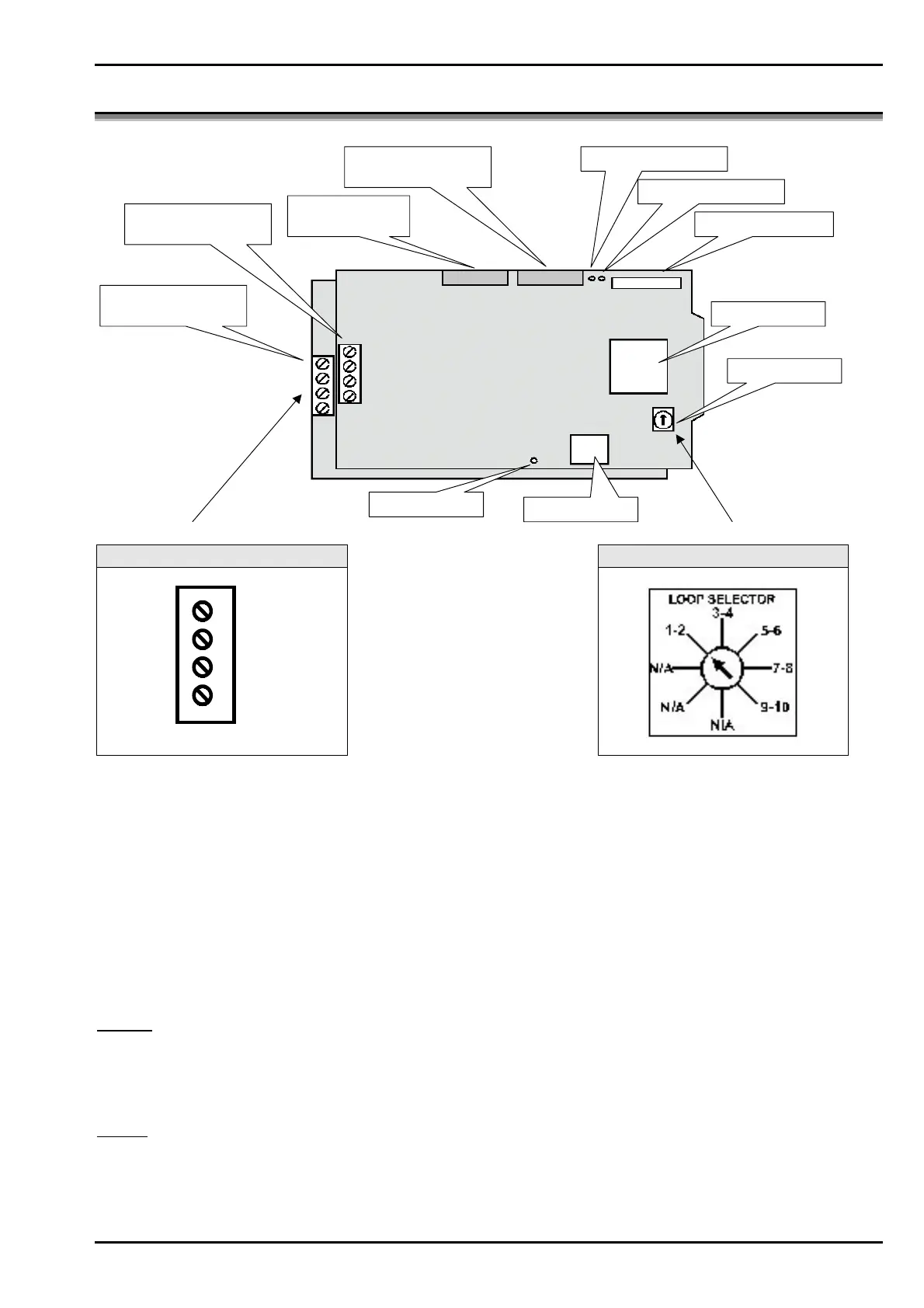
MicroController
Connector To LEM
Ground Fault on LCM
20 Way Ribbon to
next LCM
20 Way Ribbon From
LIM Or Previous LCM
Address Switch
Ground Fault on LEM
LCM Firmware
5VDC OK
First Loop
(Loops 1, 3, 5, 7, 9)
Second Loop
(Loops 2, 4, 6, 8, 10)
Loop Connections Address Switch Settings
A-
B-
A+
B+
The LCM is a 1-loop board and can support 159 detectors and 159 modules. The field wiring is electrically isolated
from the rest of the system so that any two-ground faults on separate loops will not cause invalid replies from
devices. A short to any other system circuit will not cause communication loss. The LCM has an earth fault
detection circuit with a yellow LED displaying an earth fault condition.
The LEM is an expansion board that attaches to its LCM parent providing a second loop which has the same
features as the parent loop.
Loop wiring styles:
Loops may be operated one of several modes – style 4, style 6 as well as style 7 (refer to diagrams below). Style 4
is an open loop arrangement while styles 6 and 7 are closed loop arrangements. Refer to section 4.3.8.2 for loop
configuration details and to section 5.5.2 for cabling requirements.
Style 4. (Open loop - does not return to the panel, non-redundant)
Port A (Channel A) 3810M maximum, 50 Ohms resistance maximum.
Port B (Channel B) 3810M maximum, 50 Ohms resistance maximum.
In style 4, the processor will poll both legs of the “loop” simultaneously through its own driver. If either leg is
shorted (wire-wire), the other leg is not degraded since it is operated from a separate driver.
Style 6. (Closed loop - returns to panel providing a redundant path for open circuit conditions)
Total Loop, 3810M maximum, 50 Ohms resistance maximum.
In style 6, the processor polls the loop from one of the drivers (the B-side). If a failure (open circuit) is detected, it
will poll through both ends.
www.PDF-Zoo.com

 Loading...


