Page 34 AFP-2800 - Fire Indicator Panel – Panel Operation
© N
OTIFIER
I
NERTIA
P
TY
L
TD
, 2001
WWW
.
INERTIA
.
COM
.
AU
S
ERVICE
M
ENU
- L
IST
– R
ING
– M
ODULE
L
IST
– M
ODULE
I/O L
IST
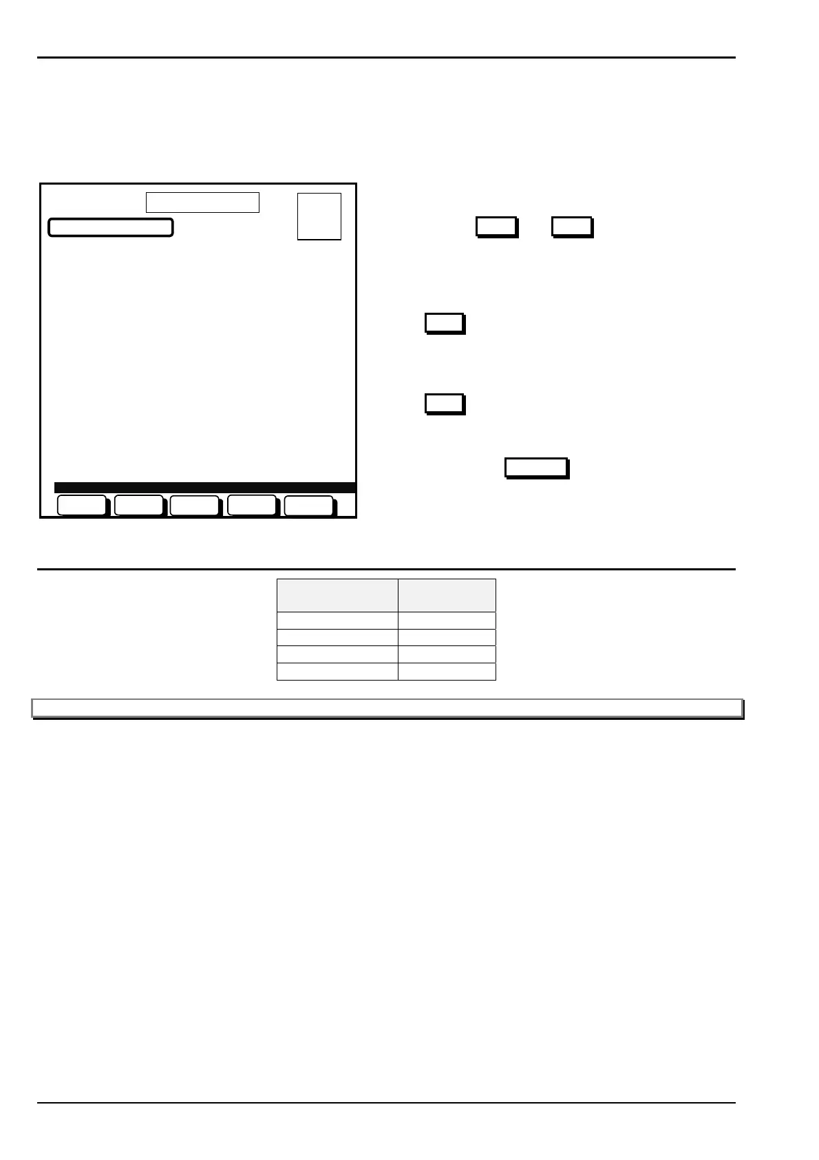
Once you have selected the module, a list of all inputs and outputs for that module will be displayed in a format
specific for the module type. The example below shows a the layout for an AZM-8 module which has 8 AZF inputs
and 4 programmable outputs.
RING 1 MODULE 1
IDENTIFIED AS AZM-8
AZF I/P STATUS O/P STATUS
Z01:I o01:
Z02:IA o02: x
Z03: o03: x
Z04:F o04:
Z05:
Z06:IF
Z07:
Z08:
ZONE 1, KITCHEN LEVEL 6
MODULE I/O LIST
01 OCT 1999 14:44:37
NEXTPREV
BACK
USE BUTTONS TO SELECT AN I/O:
A = 0
F = 0
I = 0
N = 0
TEST
CHANGE
Actions:
• Use the PREV
and NEXT buttons to scroll
through I/O points.
(The points descriptor will display at the bottom of
the screen when each point is highlighted.)
• When highlighting an AZF input point, pressing the
TEST
button will take you into the test menu for
AZF’s (refer page 51). Which provide the options for
an Alarm Test and Fault test.
• When highlighting an output point, pressing the
TEST
button will take you to a test menu for
outputs where you can toggle the output on/off for
commissioning test purposes. Refer to page 52.
• Pressing the CHANGE
button will take you to the
Modify Point Screen (refer to page 41)
In the above example, the following abbreviations of STATUS apply.
Status
Abbreviation
Meaning
AAlarm
IIsolated
FFault
X Activated
Note: If the input is a non-alarm AZF, it will display an x when the INPUT is activated.
www.PDF-Zoo.com

 Loading...


