Product Diagram Section 2 System Overview
NFS-3030 Installation PN 51330:C 10/28/2003 13
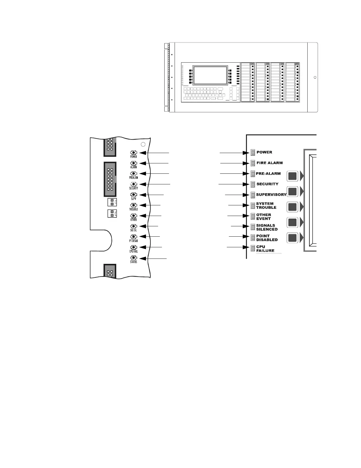
The keyboard/display
assembly is shown in
Figure 2. As shown in
Figure 3, LEDs on the
keyboard/display are
repeated on the printed
circuit board. This
enables operation and
trouble-shooting when
the panel is used without
the display assembly.
2.3.1 Main Power Supply
The AMPS-24/E addressable main power supply provides a total of 4.5 A to the CPU. During normal
operation it recharges batteries ranging in capacity from 25 to 200 amp-hours. Refer to the AMPS-24/E
Manual for details.
Refer to Section A “Electrical Specifications” to determine whether your system requires an auxiliary
power supply.
Figure 2 CPU-3030D (Shown with Two Annunciators)
CPU-3030D-ACS.cdr
Figure 3 Status Indicator LEDs
LED1 Power (Green)
LED3 Fire Alarm (Red)
LED8 Pre-Alarm (Red)
LED7 Security (Blue)
LED9 Supervisory (Yellow)
LED6 System Trouble (Yellow)
LED10 Other Event (Yellow)
LED11 Signals Silenced (Yellow)
LED12 Point Disabled (Yellow)
LED5 CPU Failure (Yellow)
LED4 Factory Use Only
LEDs on Printed Circuit Board LEDs on Keypad
3030-leds.cdr, 3030keypadleds.cdr
 Loading...


