Section 4 Applications Fire/Security Applications
52 NFS-3030 Installation PN 51330:C 10/28/2003
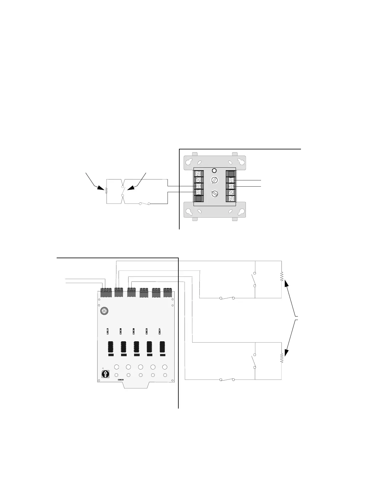
4.5.6 Wiring for Proprietary Security Alarm Applications
Typical wiring for proprietary security alarm applications with the FMM-1 module.
Note the following:
• The module is programmed with one of five type codes (see Section 4.5.2 “General Security
Requirements”).
• Supplementary use only applies to UL-listed systems.
• NAC devices used for security cannot be shared with fire NAC devices.
• Refer to the Device Compatibility Document for compatible NAC devices.
• All monitor modules used for security application must be installed in the control panel cabinet
with STS-1 Security Tamper Switch.
Figure 37 Wiring Diagram for Proprietary Security Alarm Applications
8
9
8
8
9
9
10
11
12
13
14
150
0
1
1
2
2
3
3
4
4
5
5
6
6
7
7
0
1
2
3
4
7
6
5
TENS
ONES
DDRESS
LOOP
+
FMM-1
UL-listed, normally-closed
security switch
UL-listed,
normally-open
security switch
47K
End-of-Line
Resistor
SW101
O
N
O
N
ON
O
N
SW201
S
W
3
0
1
S
W
4
0
1
O
N
S
W
5
0
1
E
n
a
b
l
e
E
n
a
b
l
e
E
n
a
b
l
e
E
n
a
b
l
e
S
W
1
0
2
SW1
S
W
2
B
a
s
e
A
d
d
r
e
s
s
SW202
SW302
SW402
E
n
a
b
l
e
S
W
5
0
2
1
0
5
7
8
6
2
3
4
9
1
5
13
12
14
1
0
T
B
4
T
B
1
TB5
T
B
2
TB6
TB3
S
L
C
B
-
B
+
A
-
A
+
B+B-B+
B
-
B+B-
B+B-B+B-
0
5
(+)
(-)
UL-listed, normally-closed
security switch
UL-listed,
normally-open
security switch
UL-listed,
normally-open
security switch
UL-listed, normally-closed
security switch
XP5-M
SLC
Channel
A or B
47K
End-of-Line
Resistor
SLC
Channel
A or B
NFS-3030 Protected Premises Unit
NFS-3030 Protected Premises Unit
3030-burglarXP5M.cdr
3030-burg-FMM.cdr
 Loading...


