Section 4 Applications Fire/Security Applications
54 NFS-3030 Installation PN 51330:C 10/28/2003
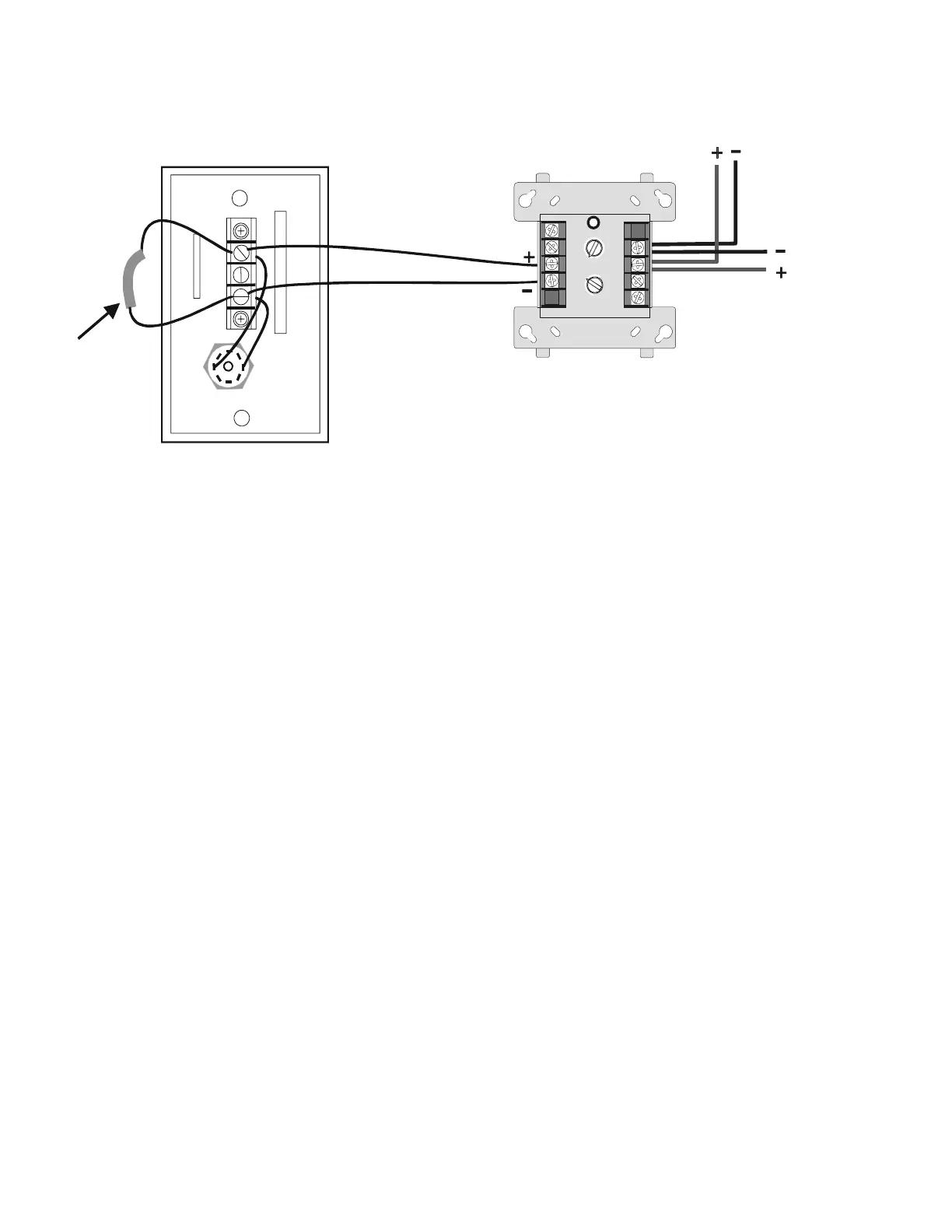
Figure 39 Connecting the FMM-1Module to the RKS-S
4.5.8 Single Tenant Security System with Entry/Exit Delay
The following system requirements are illustrated in Figure 40.
• One NFS-3030 Control Panel
• Multiple Security Supervisory Circuits Reporting to Central Station as a Single Area
• The minimum security equipment required is as follows:
—Multiple MM Monitor Modules per Protected Area
—One Group Interface for security alarm
—One Group Interface to generate trouble arming system
—Contact Switch for Each Entry/Exit Door
—RKS-S Key Switch
—MM Monitor Modules
—Remote Annunciator for Each Entry/Exit Door
(ACM-24AT, ACM-48A, ACM-16AT, ACM-32A)
—Security Devices
8
9
8
8
9
9
10
11
12
13
14
150
0
1
1
2
2
3
3
4
4
5
5
6
6
7
7
0
1
2
3
4
7
6
5
TENS
ONES
DDRESS
LOOP
RKS-S rear
FMM-1
RKSFMM-b.cdr
Signaling Line Circuit
Out
Signaling
Line Circuit
In
Wire an R-
47K End-of-
Line Resistor
into the circuit
 Loading...


