Section 4 Applications NFPA 72 Central or Remote Station Fire Alarm System (Protected Premises Unit)
48 NFS-3030 Installation PN 51330:C 10/28/2003
4.3 NFPA 72 Central or Remote Station Fire Alarm
System (Protected Premises Unit)
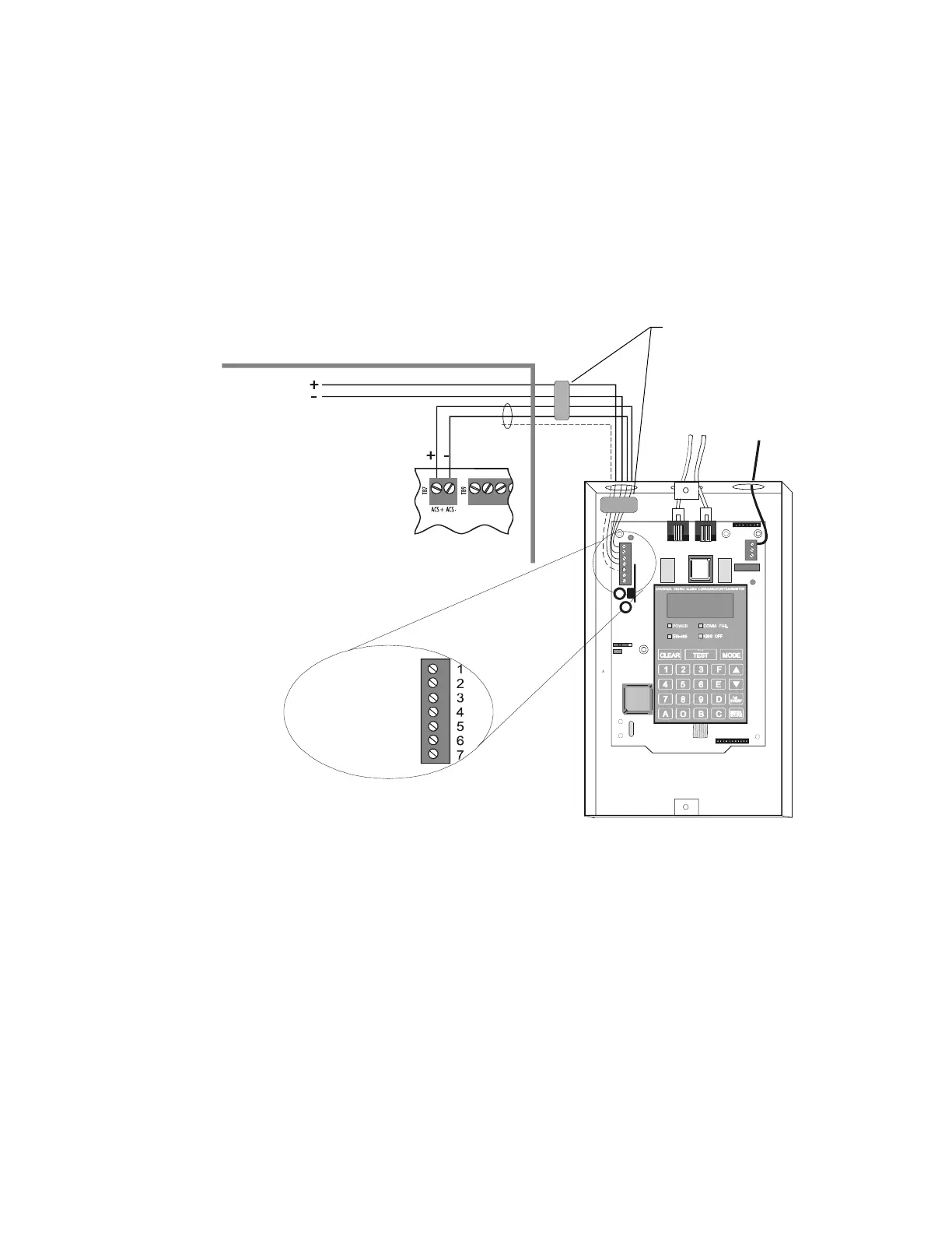
The figure below shows typical wiring diagram for a NFPA 72-1999 Central Station Fire Alarm System
(Protected Premises Unit) or a Remote Station Fire Alarm System (Protected Premises Unit) using the
Universal Digital Alarm Communicator/Transmitter (UDACT) and NFS-3030. Connect and program
the UDACT according to the directions given in The UDACT Instruction Manual.
Note: An NFPA 72-1999 Central Station requires 24 hours of standby power; an NFPA 72-1999
Remote Station requires 60 hours of standby power.
Typical wiring of a UDACT with NFS-3030:
Figure 34 Typical Wiring Diagram for a Central Station Fire Alarm System
Note: This application can also be done with the TM-4 Transmitter; refer to the TM-4 Transmitter
Module manual for more details.
Note: The following models do not comply with requirements for AC loss delay reporting and must be
used with Central Station Protected Premises systems: AA-30, AA-120, AA-100, APS-6R, CHG-120.
Note: Install a 120 ohm End-of-Line resistor
(P/N 71244) UDACT TB1 terminals 3 and 4 if
last or only device on EIA-485 line.
UDACT in ABS-8RB
(shown with cover removed)
Solid earth
ground
To supervised
phone lines
FACP Cabinet
EIA-485 (ACS Mode)
TB7 on control panel
Supervised and power-limited
EIA-485 and power wiring
3030-UDACT.cdr
+24 VDC
non-resettable
power from main
or auxiliary power
supply
+24V
Gnd
RS+
RS-
Shield
RS+
RS-
ACS/Term
TERM (NC)
Ferrite cores
P/N 29090
 Loading...


