Attaching the CPU & Chassis Section 3 Installation
NFS-3030 Installation PN 51330:C 10/28/2003 21
separation of power-limited and non-power-limited wiring; for example, having all non-power-limited
circuits grouped in one area of the cabinet (see Section 3.16 “UL Power-limited Wiring Requirements”
and your power supply manual).
3.5 Attaching the CPU & Chassis
Mount CPU into positions 1 and 2 of CHS-M3 as follows; equipment may be mounted to the chassis
before or after the chassis is mounted in the backbox. Some equipment may be door-mounted directly in
front of the CPU; see Section 3.4 “Laying Out Equipment in Cabinet and Chassis” and the manual
shipped with the other device.
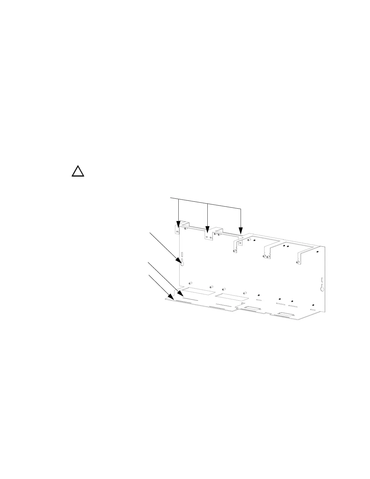
1. Attach four stand-offs to chassis as shown in Figure 7.
CPU-3030D (with keypad/display) requires the longer stand-offs: 1.5 inch (38.1 mm);
CPU-3030ND (without keypad/display) requires the shorter stand-offs: 0.25 inch (6.35 mm)
2. Slide circuit-board tabs into slots on chassis as shown in Figure 7.
3. Place the board over the stand-offs so that mounting holes line up with those on the chassis. Secure
all stand-offs with screws provided.
Figure 7 Standoffs on Chassis CHS-M3
Note for CPU-3030D: Due to the difficulty of reaching under the keypad, it may be convenient to
remove the insulator from the lithium memory-backup battery at this time. See Section 3.5.1 “Memory-
Backup Battery”.
Mounting Chassis in Backbox
Align chassis-mounting slots with chassis-mounting studs (see Figure 4 and Figure 7 for locations).
Secure with nut & lock-washer provided with chassis.
!
CAUTION: It is critical that all mounting holes of the NFS-3030 are secured with a screw or
stand-off to insure continuity of Earth Ground.
CPU standoffs at
Positions 1 and 2:
1 inch (25.4 mm)
CHS-M3.cdr
CPU-3030ND
(without keypad/display)
CPU-3030D
(with keypad/display)
Chassis-mounting slots
 Loading...


