Form-C Relays on the CPU Section 3 Installation
NFS-3030 Installation PN 51330:C 10/28/2003 37
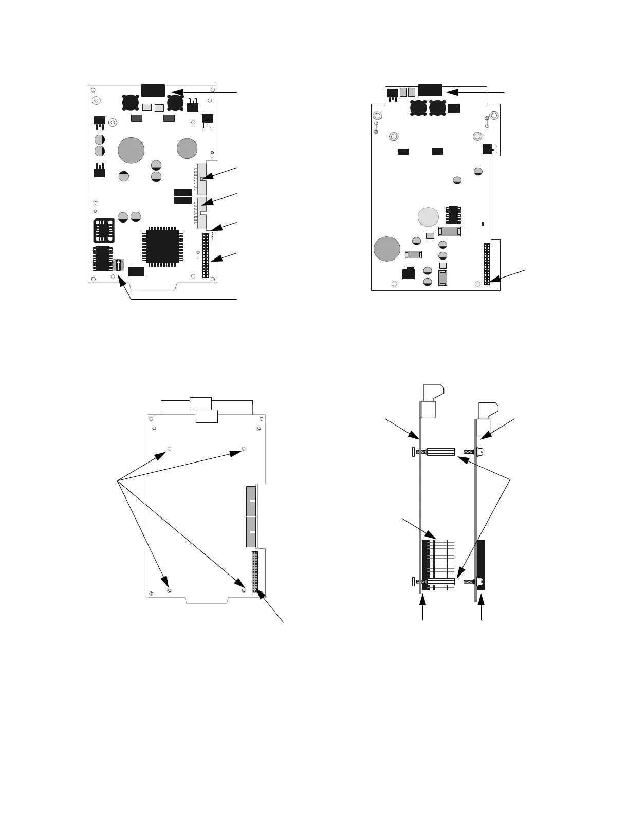
Figure 23 LCM-320 & LEM-320 Diagram
Figure 24 Connecting LCM-320 with LEM-320
J3
J1
J2
JP1
D33
+5V
D32
D28
SLC
B+ A+ B- A-
JP2
TB1
JP3
SW1
EG
FAULT
B+ A+ B- A-
TB1
J1
JP1
SW1 Set to assign a unique
SLC loop number
J3 Data Out to next LCM-320
J1 Data In from control panel
or from previous LCM-320
Ground Fault LEDs:
D32 LEM-320 Ground Fault
D28 LCM-320 Ground Fault
J2 LEM-320
Connection
TB1 SLC Loop
Connection
LCM-320
Connection
LCM-320 LEM-320
Note: Do not cut any jumpers on LCM-320 or LEM-320
TB1 SLC Loop
Connection
LCM-320.cdr
LEM-320.cdr
J2
SLC
B+ A+ B- A-
TB1
J1
J1
Stand-off
locations
J2 on LCM-320
“LEM-320 Data”
LEM mounted behind LCM
LEM-LCM.cdr
Stand-offs
0.937 inch
(23.8 mm)
J1 on
LEM-320
J2 on
LCM-320
Loop
expander
module
(in back)
Loop
control
module
(in front)
Stacker-
Connector
0.937 inch
(23.8 mm)
LEM-LCM-side.cdr
 Loading...


