Attaching Panel Circuit Modules Section 3 Installation
NFS-3030 Installation PN 51330:C 10/28/2003 23
Note:
1. Install four 1 inch (25.4 mm) stand-offs onto the chassis as shown in Figure 8.
2. Place the first option board over the stand-offs so that holes line up.
3. If no more option boards will be mounted in that position, securely fasten all stand-offs with screws
(provided with module). If mounting a second or third option board, attach another layer of stand-
offs and repeat steps 2-3. Note: Set the switches on an option board before mounting another layer
in front of it.
4. If mounting a pair of SLC loop modules, refer to Section 3.14.2 “Loop Control Module, Loop
Expander Module” and to Section 3.7.3 “Installing a Multi-layer Module into the Chassis”.
5. For the top (fourth) layer of option boards, slide the tab at the bottom of the board into the slots on
the chassis, and lay the board back onto the top of the chassis so that the studs line up with
mounting holes on the option board. Securely fasten all stand-offs with screws provided with
module.
6. If mounting the option board behind a blank module plate in a dress plate or annunciator backbox,
see the BMP-1 Product Installation Drawing for details. This dress plate is suitable for option
boards, which do not need to be visible or accessible when the door is closed.
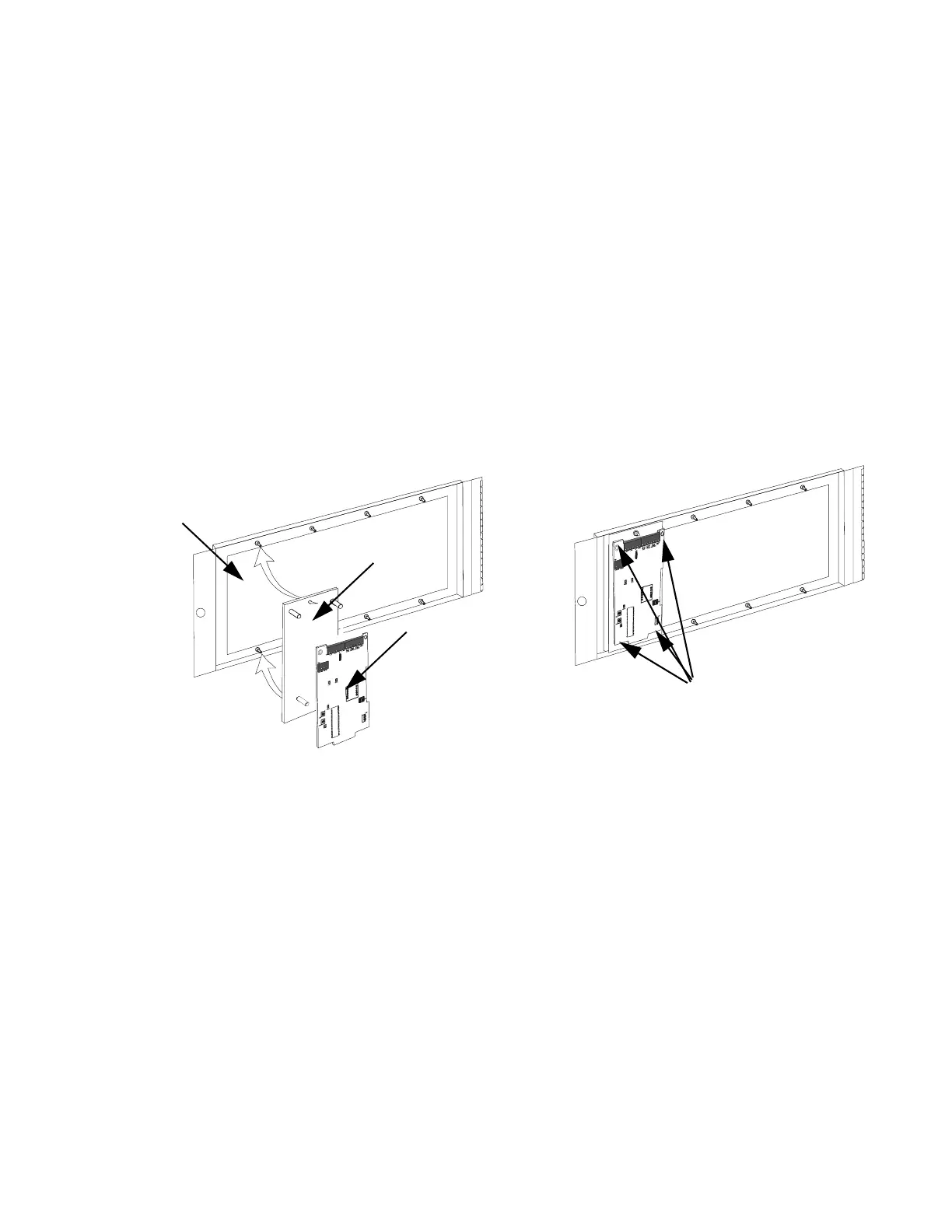
Figure 9 Mounting Single-space Blank Plate with Option Board
7. If mounting a pair of loop control/expander modules, see Section 3.14.2 “Loop Control Module,
Loop Expander Module”.
3.7 Attaching Panel Circuit Modules
3.7.1 Overview
If installing panel circuit modules into a CAB-4 Series backbox, mount and connect those boards at this
time. This section contains general instructions for mounting a panel circuit module; see the sections
about individual panel circuit modules for module-specific instructions. For voice alarm/evacuation
applications (VCM-4RK and DCM-4RK), see the Voice Alarm System Manual.
• Mount an optional expander board to the module.
• Install the panel module onto a chassis.
• Connect ribbon cables from CPU.
• Connect ICM-4RK and ICE-4 modules to the power supply.
• Connect NACs, IDCs, and relays; write any non-power-limited relay connections on door label.
• Field wire the module.
• After powering up the system, program the panel.
Single-space
blank plate
Fasten option board to the
plate with four screws
(included).
tm4adp4.cdr
Mount option board
onto stand-offs on the
blank plate
Mount single-space blank plate
onto compatible dress panel
Note: Mounting instructions for option boards are the same in vari-
ous dress panels.
 Loading...


