NACs with ICM-4RK⁄ICE-4 Section 3 Installation
NFS-3030 Installation PN 51330:C 10/28/2003 29
3.9 NACs with ICM-4RK⁄ICE-4
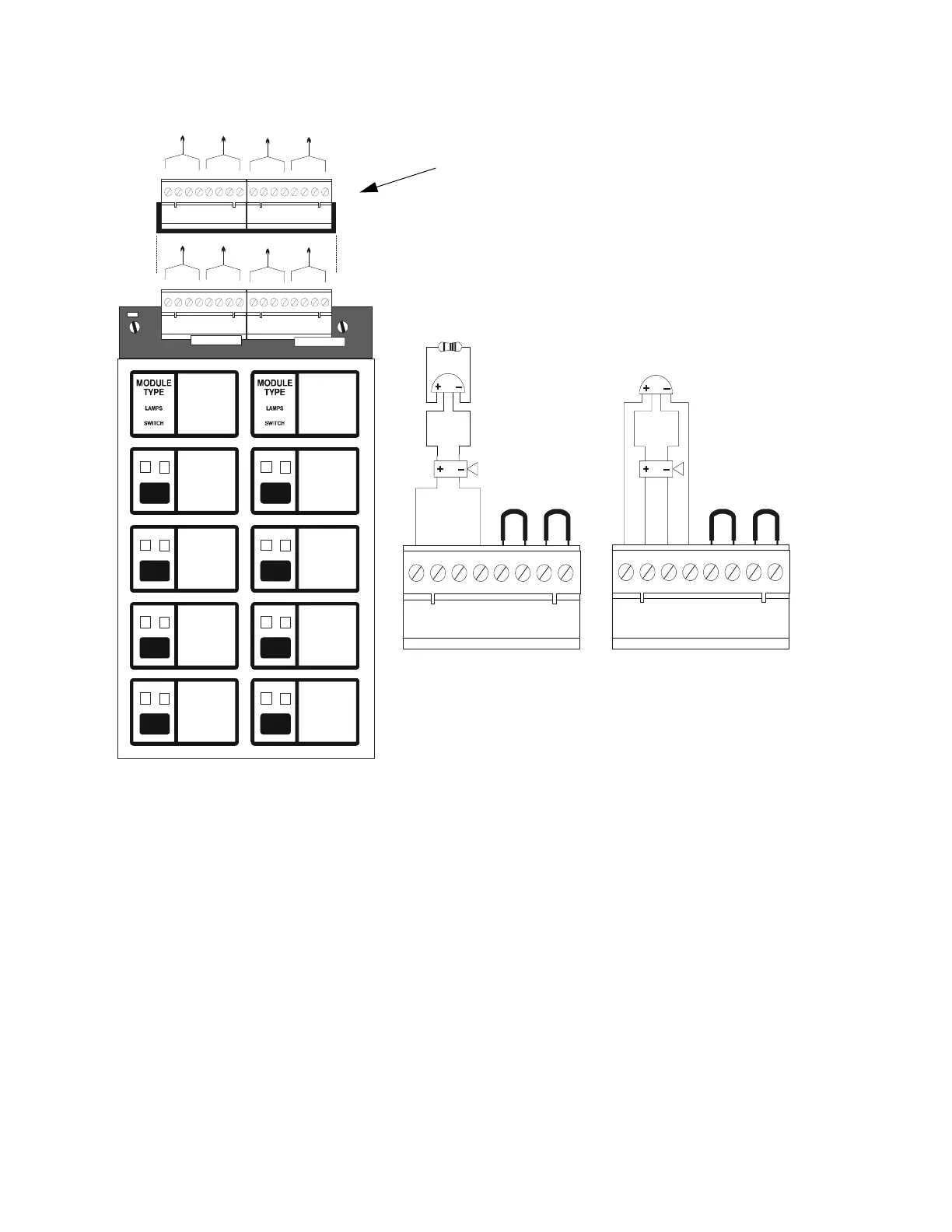
Figure 15 Field-Wiring an ICM-4RK/ICE-4: NFPA Style Y, Z
1. Notification circuits are supervised, power limited and may be connected to energy-limited cable.
2. Use only the compatible, UL-listed Notification Appliances listed in Device Compatibility
Document.
3. Wire Notification Appliances according to the manufacturer's instructions packaged with each
device.
4. Maximum current per circuit is 3.0 A. Maximum current per module depends on the type of power
supply (standard or auxiliary).
5. Canadian installations require model N-ELR End-of-Line Resistor Assembly (Style Y only).
6. Size the NAC wiring so the voltage drop does not exceed the minimum rated voltage of the
notification appliance used as the last device on the circuit.
7. For zone coded applications, see the UZC-256 Universal Zone Coder manual.
8. For power wiring see Figure 17.
9. The ICM-4RK is California Code programmable (microprocessor P/N 34077 Rev. B or higher). To
program for California Code, cut diode D35 as shown in Figure 16 .
A
B
C
D
A
B
C
D
H
G
E
F
INITIATING
ZONE
RED = ALARM
YELLOW = TROUBLE
DISPLAY PROGRAM
INITIATING
ZONE
RED = ALARM
YELLOW = TROUBLE
DISPLAY PROGRAM
b+ a+ a- b-
b+ a+ a- b-
b+ a+ a- b-
b+ a+ a- b-
F
G
H
b+ a+ a- b-
b+ a+ a- b-
b+ a+ a- b-
b+ a+ a- b-
ICB
B+ A+ A– B– B+ A+ A– B– B+ A+ A– B– B+ A+ A– B–
Optional ICE-4 Indicating Circuit Expander.
Positions E, F, G, and H are active only with this board installed.
Note that CRE-4 expander may also be installed on the ICM-4RK.
Jumpers for
unused circuits
4.7K, 1/2 watt ELR
5
P/N 71252
UL/ULC-listed
24 VDC Polarized
Devices
ICM4wire-StyleYZ.cdr
Typical NFPA
Style Y (Class B)
Notification Appliance
Circuit
Jumpers for
unused circuits
Typical NFPA
Style Z (Class A)
Notification Appliance
Circuit
 Loading...


