Initiating Device Circuits with IZM-8RK/IZE-A Section 3 Installation
NFS-3030 Installation PN 51330:C 10/28/2003 27
3.8 Initiating Device Circuits with IZM-8RK/IZE-A
3.8.1 Style B Field Wiring
IZM-8RK Initiating Zone Module for up to eight Style B Initiating Device Circuits.
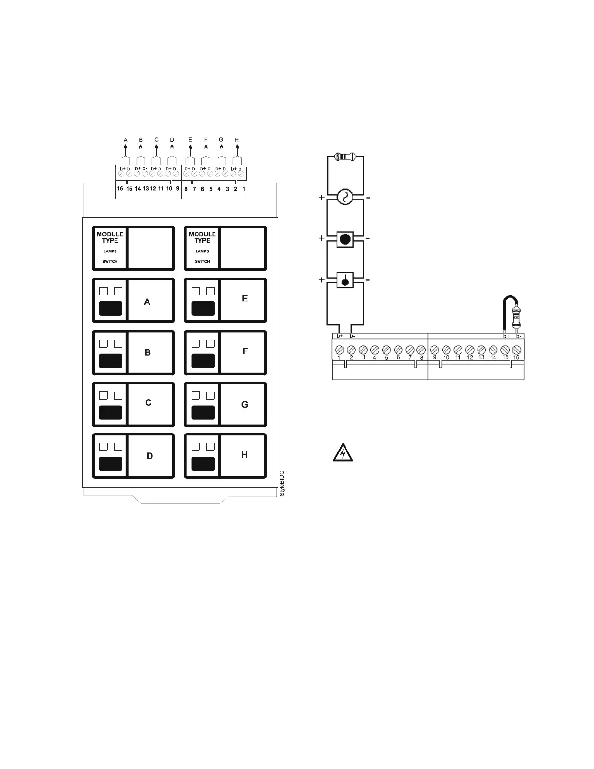
Figure 13 NFPA Style B Field Wiring of the IZM-8RK Initiating Zone Module
1. Initiating Device Circuits are supervised, power-limited and may be connected to limited-energy
cable. Initiating devices include non-coded manual pull station, heat detectors, photo and ion
detectors, waterflow alarm and waterflow supervisory devices. Connect waterflow alarm devices to
a dedicated circuit, programmed for waterflow option. Connect N.O. waterflow supervisory
devices to a dedicated zone programmed for supervisory operation. The terminal blocks will accept
12AWG to 22AWG wire. Initiating circuit current will ensure alarming of one two-wire detector
only.
2. Use only the compatible, UL/ULC-listed two-wire smoke detectors that are listed in the Device
Compatibility Document.
3. For connection of 4-wire smoke detectors and initiating devices requiring separate 24 VDC power,
refer to your power supply manual and to the wiring diagrams shipped with your devices.
4. Wire initiating devices according to the manufacturer's instructions packaged with each device.
5. For Canada, model N-ELR End-of-Line Resistor Assembly required.
6. Maximum line resistance due to wiring is 100 ohms.
4.7K, 1/2 watt ELR (71252)
5
UL/ULC-listed two-wire smoke detector
2
Manual Pull Station
Heat Detector
Dummy load all
unused circuits
with 4.7K ELR
(71245)
Typical NFPA Style B Initiating Device Circuit
!
WARNING: Do not mix fire alarm
points with non-fire alarm points on the
same IZM-8RK/IZE-A Initiation Zone
Module.
 Loading...


