44205401TH Rev.1
74 /
Oki Data CONFIDENTIAL
4. Component replacement
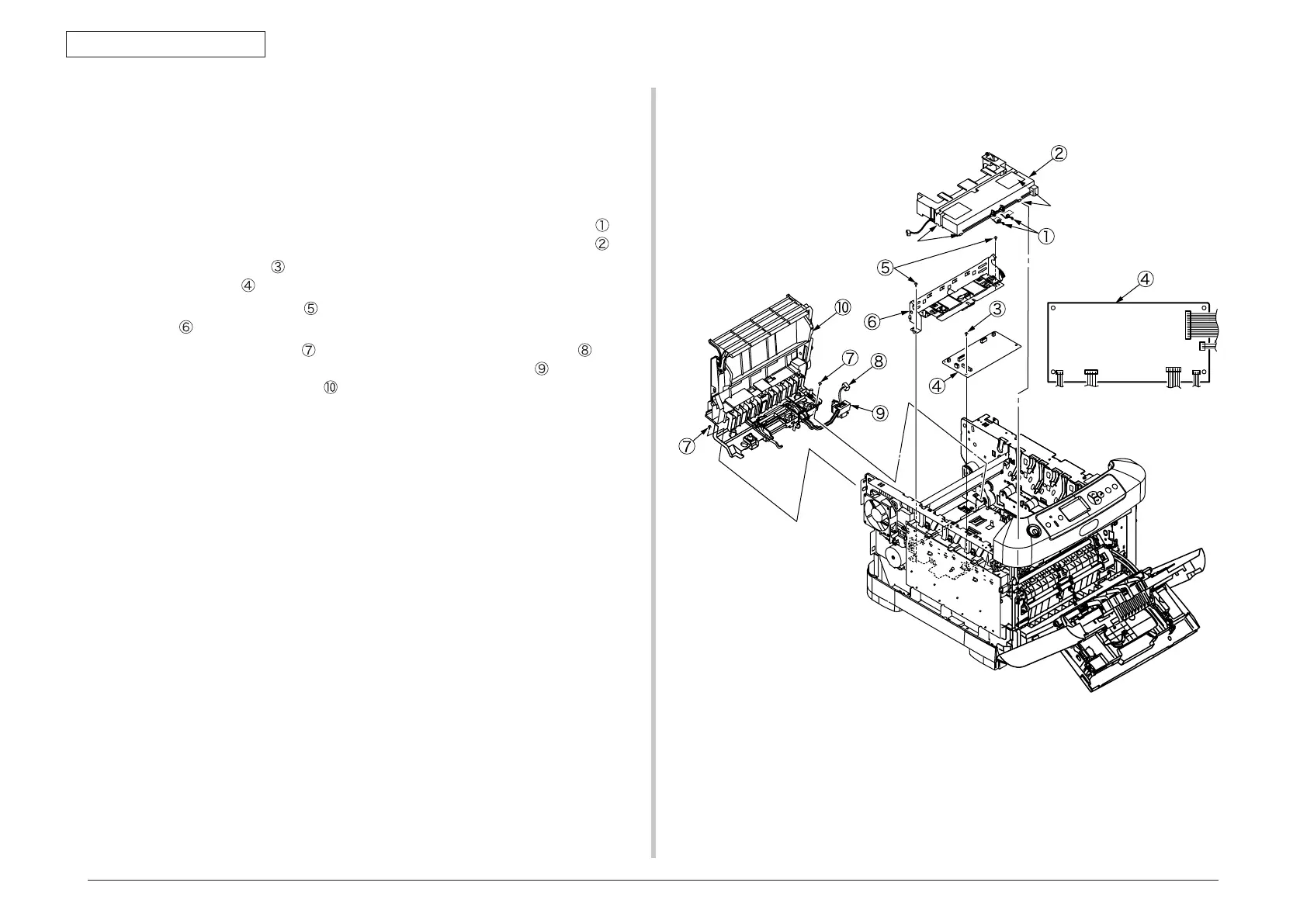
4.2.15 Guide eject Assy/ Color regist Assy/ Board-PRY
(1) Remove the left side cover, right side cover, rear cover, top cover Assy. (See
section 4.2.3, 4.2.4, 4.2.6, 4.2.9)
(2) Re
move the control PCB and low-voltage power supply. (See section 4.2.8,
4.2.14(3))
(3) Remov
e the connector of belt thermistor, remove the two torsion springs
, and
disengage four claws (4 places) by minus driver, remove the cover driver
.
(4) Remove the screws
(silver, No:42920406) and connectors (6 places), remove
the Board PRY
.
(5) Remove the two screws
(silver, No:42920406) and remove the color regist
Assy
.
(6) Remove the two screws
(silver, No:42920406), remove the cable of fuse
I/F connector from clamp, and slide the claw of cable guide
to disengage,
remove the guide eject Assy
.
FUSER
LCR
RCR
DENS
EXIT
PUIF
Claw
Claw
 Loading...