3-5-3
Operation Indicators
The LED indicator shows the unit operating status of the Analog Input Unit.
The operating statuses corresponding to the colors and statuses of the indicators are shown below
.
Indicator name Color Status Description
PWR Green ON Power is supplied.
OFF Power is not being supplied.
3-5-4
Address Switch Setting
This Unit is equipped with an IC that has the same interface as a PMAC3 style DSPGate3 IC.
Refer to the Power PMAC User's Manual (Cat. No. O014) for the PMAC3 style DSPGate3 IC.
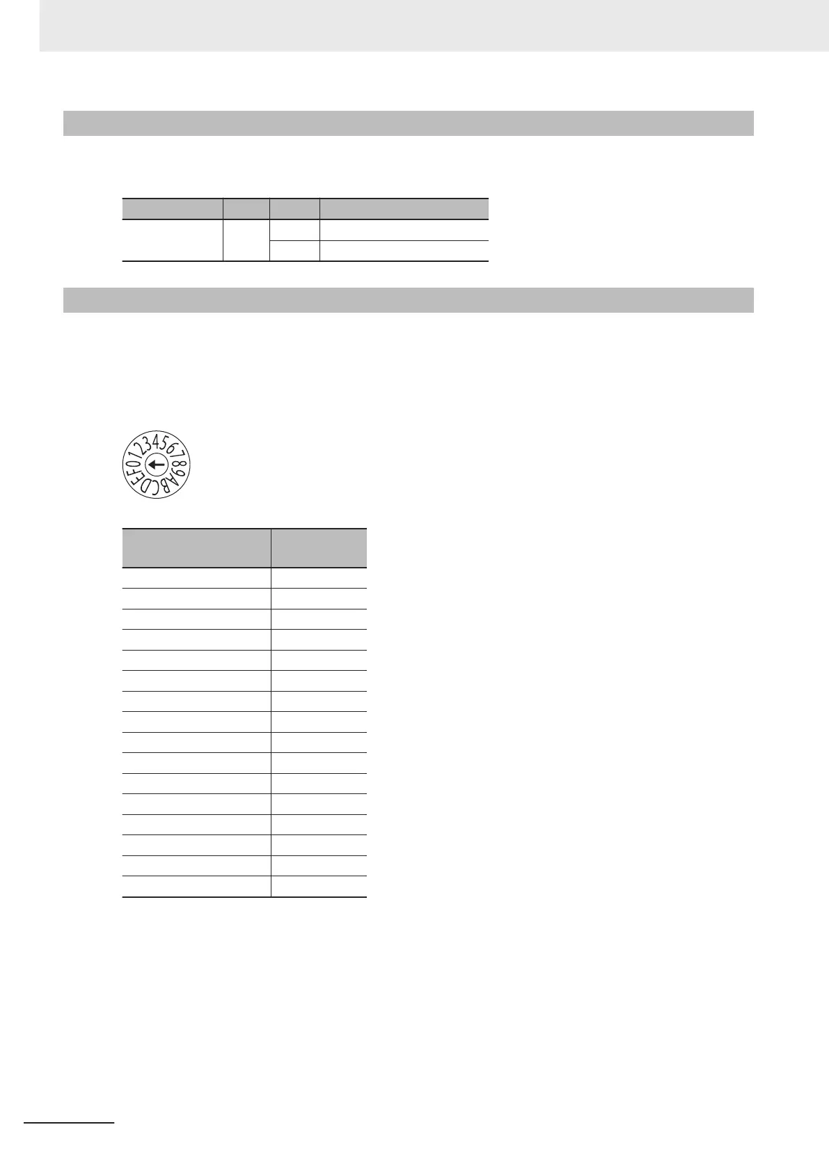
The address switch settings are used to set the Gate3 Index.
The setting range is from 0 to F. (Factory setting: 0)
Address switch setting
Power PMAC
“Gate3” Index
0 0
1 1
2 2
3 3
4 4
5 5
6 6
7 7
8 8
9 9
A 10
B 11
C 12
D 13
E 14
F 15
For example, if the address switch setting is 0, the Gate3 Index becomes 0.
In this case, this Unit is accessed with a Gate3[0] data structure.
Make sure that the address switch settings of Units do not overlap.
If they overlap, the Sys.Status register CK3WConfigErr becomes 7.
Refer to 6-4 Sys.Status Register on page 6-10 for Sys.Status.
One CK3W Unit in the system supplies servo clock and phase clock signals to all the other Units.
The supply-source CK3W Unit must be installed to the CPU Rack.
3 Configuration Units
3-56
CK3M-series Programmable Multi-Axis Controller User's Manual Hardware (O036)
 Loading...