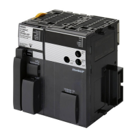
Connection diagram
Connector shell
O
utFlagB
GND
For the GND, use an encoder power source (GND).
*1.
This function is available with the CK3W-AX1313£/-AX1414£/-AX1515£ Units.
*2. With single-ended input, only a voltage output type encoder can be connected. Open collector type encod-
ers cannot be connected.
*3.
This function is available with the CK3W-AX2323£ Units.
*4. The maximum input frequency in normal specification is 2 MHz, however, you can use the connector with
frequency up to 8 MHz in the following conditions.
• Set Gate3[i].EncClockDiv=1 to use with the input frequency of 2 MHz or higher.
Set Gate3[i].EncClockDiv=3 (Default) to use with the maximum input frequency of 2 MHz or lower.
• A temporary error of four counts in the integer part (Position fluctuation) may occur periodically with the
input frequency of 1.5 MHz or higher
, however, the errors are not accumulated.
The error does not occur with the frequency of 1.5 MHz or lower and the position is output normally.
Use with the frequency of 2 MHz or lower when the temporary error during operation is an issue.
• Gate3[i].Chan[j].SosError may occur with the frequency of 2 MHz or higher.
Use a user program to check the encoder loss detection using Gate3[i].Chan[j].SumOfSquares and with-
out using Gate3[i].Chan[j].SosError.
When you set Gate3[i].Chan[j].SumOfSquares, set the threshold value to half of the value of
Gate3[i].Chan[j].SumOfSquares when operated with the maximum input frequency.
*5. A Hall sensor is a sensor that detects the rotor position of the motor by detecting the magnetic field. This is
normally used to check the position when the power is turned ON.
*6. HALL T is not normally used, however, it can be used as a general 5V digital input.
*7.
This output function is available with the CK3W-AX1414£/1515£ Units.
3-3-6
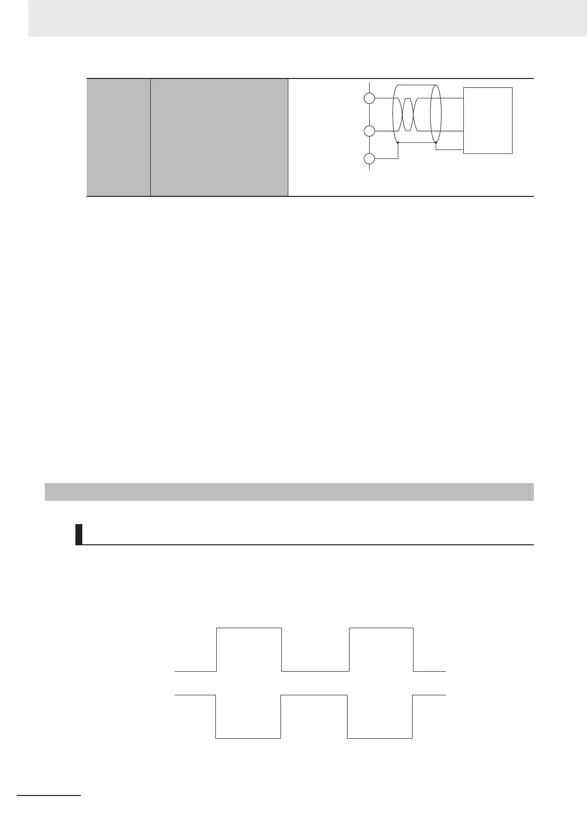
Encoder Loss Detection
Encoder Loss Detection in Digital Quadrature Encoder
Encoder loss detection is a function for detecting the encoder detachment. It can detect the encoder
loss, and stop the motor.
In the differential input for the digital quadrature encoder, when a correct signal arrives in encoder A
+/A-, encoder B+/B-, if the signal level is H in one side, the signal level of the other side is always L.
L
H
L
H
L
H
H
L
H
L
En
coder A+/B+
Encoder A-/B-
You can detect the encoder loss by setting a circuit so that both signals turn H or L when the encoder
is not connected.
3 Configuration Units
3-22
CK3M-series Programmable Multi-Axis Controller User's Manual Hardware (O036)
 Loading...