5-7
Laser Interface Unit
This section describes the wiring for the Laser Interface Unit.
5-7-1
Galvo Scanner Connector Wiring
The XY2-100 Interface connector wiring, SL2-100 Interface connector wiring, and dedicated cables
are described below.
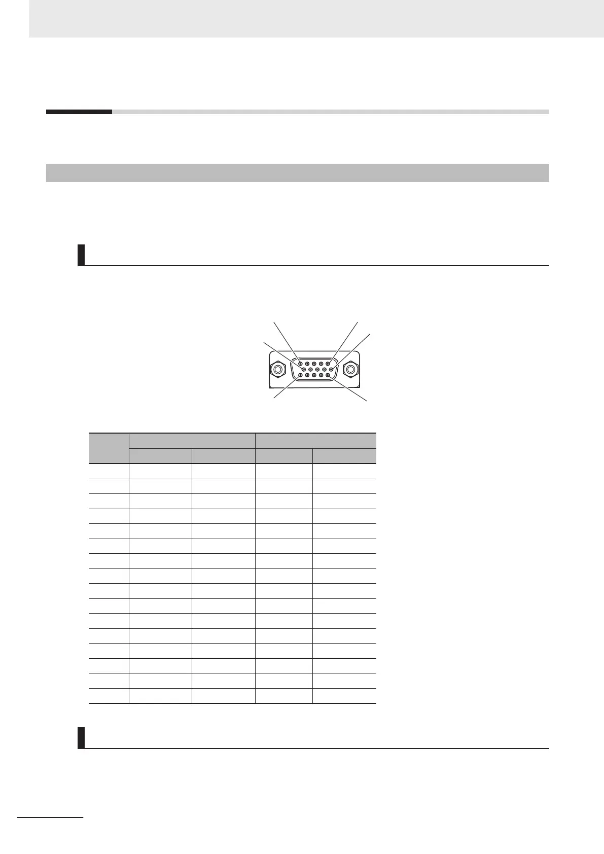
XY2-100 Interface Wiring
The Unit side connector is a high-density D-sub 15-pin female connector (MIL-C-24308 compliant,
lock screw #4-40 UNC).
Pin No.
XY Z
Signal Input/Output Signal Input/Output
1 CHX+ Output CHZ+ Output
2 CHY+ Output NC -
3 XY-SYNC+ Output Z-SYNC+ Output
4 XY-CLOCK+ Output Z-CLOCK+ Output
5 XY-STATUS+ Input Z-STATUS+ Input
6 CHX- Output CHZ- Output
7 CHY- Output NC -
8 XY-SYNC- Output Z-SYNC- Output
9 XY-CLOCK- Output Z-CLOCK- Output
10 XY-STATUS- Input Z-STATUS- Input
11 NC - NC -
12 NC - NC -
13 GND Common GND Common
14 GND Common GND Common
15 NC - NC -
Shell Shield Shield
SL2-100 Interface Wiring
The Unit side connector is a high-density D-sub 15-pin female connector (MIL-C-24308 compliant,
lock screw #4-40 UNC).
5 Wiring
5-46
CK3M-series Programmable Multi-Axis Controller User's Manual Hardware (O036)
 Loading...