Minimum switch-
ing capacity
5 VDC, 1 mA
Relay service life 100,000 operations
ON/OFF re-
sponse time
10 ms max./10 ms max.
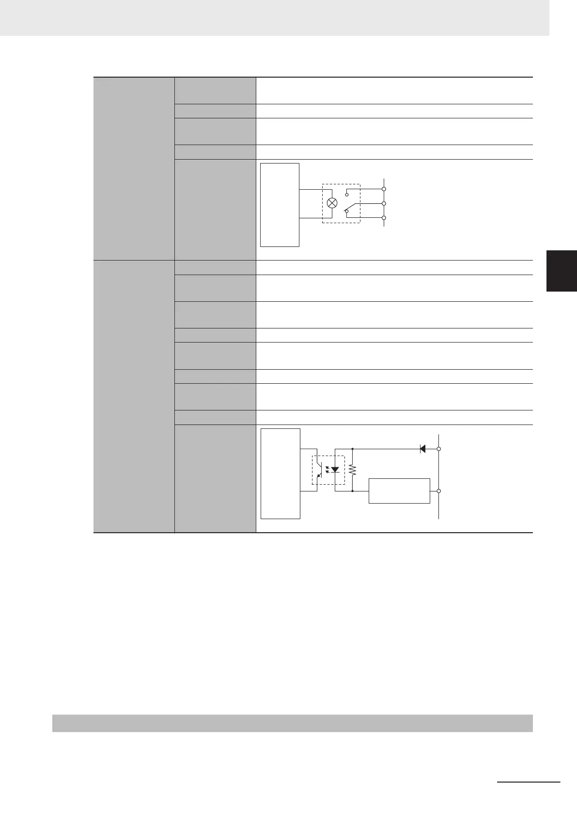
Isolation method Isolation by Relay (between amp enable output and internal circuit)
Circuit configura-
tion
Internal
ci
rcuit
Amp enable NO
Amp enable common
Amp enable NC
Fault input
*2
Number of inputs 1 point/channel
Rated input volt-
age
5 to 24 VDC
Maximum input
voltage
26.4 VDC
Input current 7 mA typical (24 VDC)
ON voltage/ON
current
3 VDC min./1 mA min.
OFF current 0.1 mA max.
ON/OFF re-
sponse time
20 μs min./400 μs max.
Isolation method Isolation by Photocoupler (between fault input and internal circuit)
Circuit configura-
tion
Fault input +
Internal
circuit
Fault input -
Current
control circuit
*1. In DACA-, the reversed voltage of the DACA+ is output. In other words, when DACA+ = +10 V, then DACA-
= -10 V. In this case, between DACA+ and DACA-, a 20 V potential dif
ference is generated. The same ap-
plies to DACB+/DACB-.
*2.
Available with the CK3W-AX1414£/1515£ Units.
*3. Pulses may be output unintendedly during the initial state and startup.
Be sure to connect the amplifier enable NO output to the amplifier enable input on the amplifier side to pre-
vent motor malfunction.
Some amplifiers may have an amplifier disable input instead of an amplifier enable input. In that case, con-
nect it to the amplifier enable NC.
The above wiring is an example, so please wire according to the manual of the amplifier.
*4.
For connection with a Servo Drive with 5-VDC photocoupler input, only CK3W-AX1414£
/-AX1515£ Units
whose date of production is July 1, 2019 or later (Lot number 01719K and later) are available.
Refer to A-6 How to Read the Lot Number on page A-13 for the lot number
.
3-3-11
DA Output Method
The following two methods are available for DA output.
•
FilteredPWM
3 Configuration Units
3-31
CK3M-series Programmable Multi-Axis Controller User's Manual Hardware (O036)
3-3 Axis Interface Unit
3
3-3-11 DA Output Method
 Loading...