Note 1. Connect the cable shield to the connector hood at both ends of the cable.
Note 2. There are two connection methods for Ethernet: T568A and T568B. The T568A connection method
is shown above, but the T568B connection method can also be used.
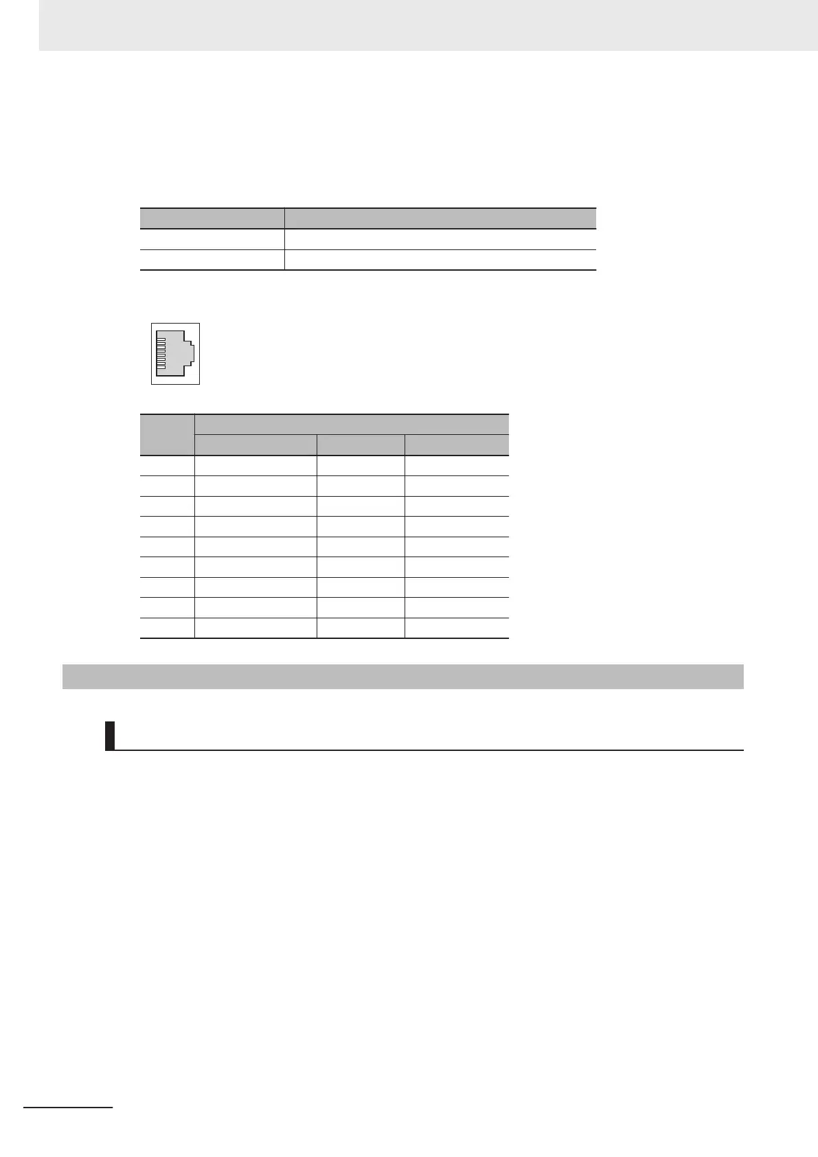
The connector specifications are as follows.
Item Specification
Electrical characteristics Conforms to IEEE 802.3 standards.
Connector structure RJ45 8-pin modular connector (Conforms to ISO 8877)
The pin assignments are as follows.
Pin No.
100BASE-TX
Signal name Abbreviation Signal direction
1 Transmission data + TD+ Output
2 Transmission data − TD− Output
3 Reception data + RD+ Input
4 Not used. --- ---
5 Not used. --- ---
6 Reception data − RD− Input
7 Not used. --- ---
8 Not used. --- ---
Hood Frame ground FG ---
5-2-3
Watchdog Timer Output Wiring
Applicable Wires
The wires that you can connect to the terminal block are twisted wires, solid wires, and ferrules that
are attached to the twisted wires. The following section describes the dimensions and processing
methods for applicable wires.
Using Ferrules
If you use ferrules, attach the twisted wires to them.
Observe the application instructions for your ferrules for the wire stripping length when attaching
ferrules.
Always use plated one-pin ferrules. Do not use unplated ferrules or two-pin ferrules.
The applicable ferrules, wires, and crimping tools are listed in the following table.
5 Wiring
5-14
CK3M-series Programmable Multi-Axis Controller User's Manual Hardware (O036)
 Loading...