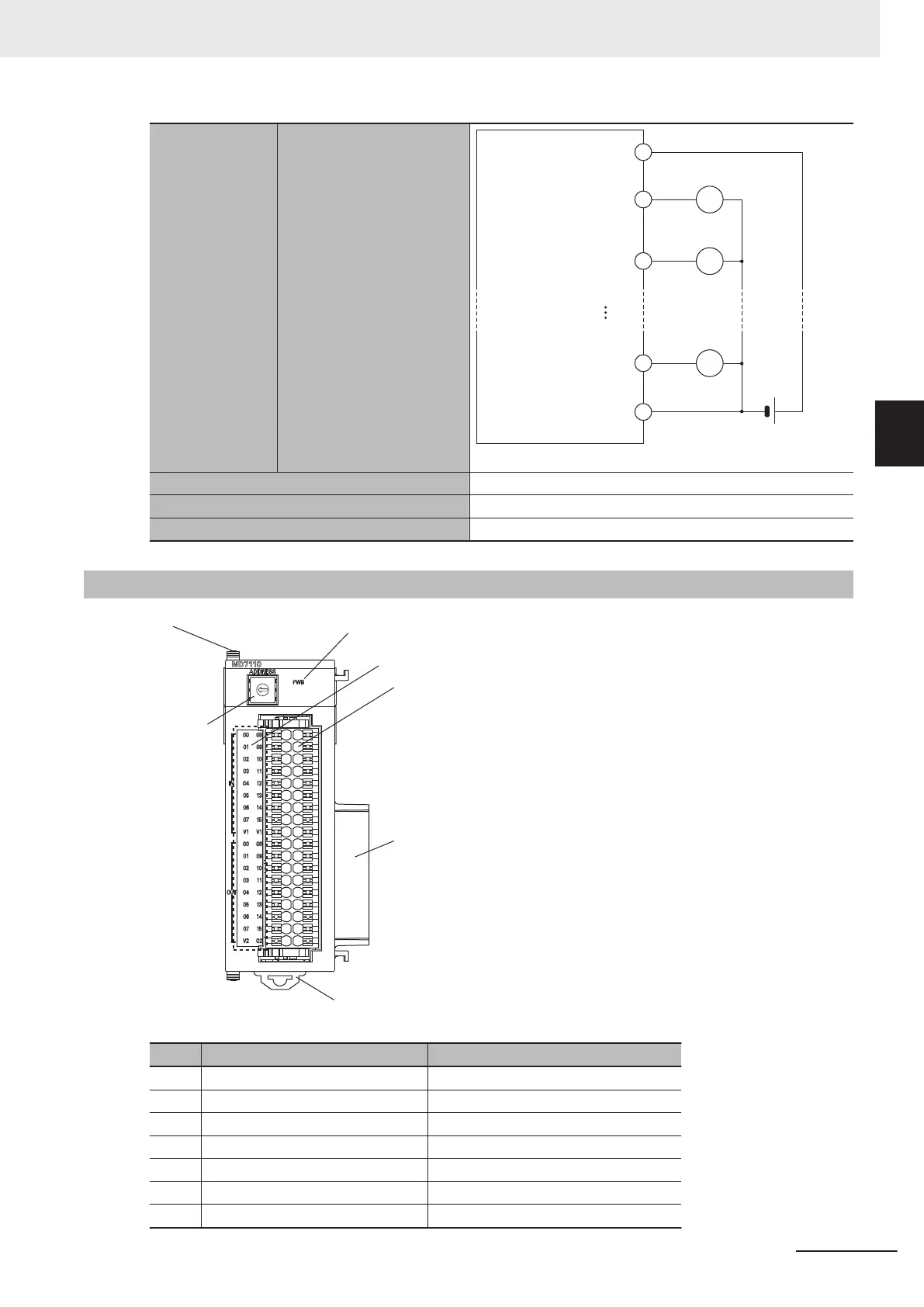
Connection diagram
12 to 24 VDC
V2
OUT
00
OUT01
OUT15
G2
L
L
L
Power consumption 5 V: 1.0 W max.
Dimensions (height × depth × width) 90(H)/80(D)/31.6(W)
Weight 150 g max.
3-4-2
Part Names and Functions
Letter Name Function
A Slider Holds the Units together.
B Power supply status indicator Shows the power supply status.
C Digital input/output status indicator Shows the digital input/output status.
D Terminal block Connects the digital input/output.
E Unit connector Connector that connects to the Unit.
F DIN Track mounting hook Used to mount the Unit to a DIN Track.
G Address switch Sets the Gate3 Index.
3 Configuration Units
3-49
CK3M-series Programmable Multi-Axis Controller User's Manual Hardware (O036)
3-4 Digital I/O Unit
3
3-4-2 Part Names and Functions
 Loading...