OutFlagD Function
Applications
When connecting with the OMRON G5-series Servo Drives with General-purpose Pulse Train or
Analog Inputs, the encoder A+/- terminal and the serial encoder DAT+/- terminal are short circuited
and used to enable obtaining the absolute encoder value sent from the Servo Drive.
Use this function to disable the terminating resistance of the serial encoder DAT+/- terminal, be-
cause the terminating resistances of the short-circuited encoder A+/- terminal and the serial encod-
er DA
T +/- terminal overlap.
Details on the Function
You can enable or disable the terminating resistance of the serial encoder DAT+/- terminal as
shown in the table below by setting the Gate3[i].Chan[j].OutFlagD register and the
Gate3[i].Chan[j].SerialEncEna register, which is for switching between enabling and disabling the
serial encoder.
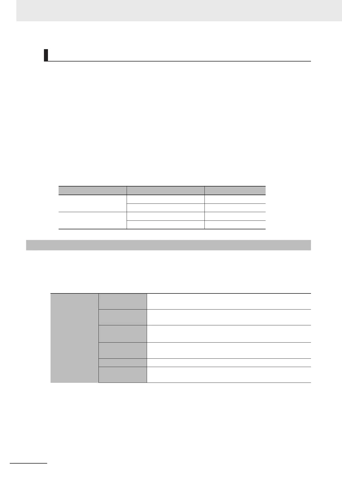
Gate3[i].Chan[j].OutFlagD Gate3[i].Chan[j].SerialEncEna Terminating resistance
0 (Default) 0 (Default) Disabled
1 Enabled
1 0 Disabled
1 Disabled
3-3-10
Amplifier Connector Specifications
This section describes the connector arrangement and electrical specifications for the amplifier con-
nector
.
For the connector arrangement of the amplifier connector
, refer to 5-3-2 Amplifier Connector Wiring on
page 5-24.
Analog output
(FilteredPWM
type)
Number of out-
puts
1 point/channel
Output method Between DACA+ and DACA-: Differential output
Between DACA+ and AGND: Single-ended output
Output range
Between DACA+ and DACA-: -20 to 20V
*1
Between DACA+ and AGND: -10 to 10V
Allowable load
resistance
5 kΩ min.
Resolution Refer to 3-3-11 DA Output Method
on page 3-31.
Isolation method Isolation by Digital Isolator (between analog output and internal cir-
cuit)
3 Configuration Units
3-28
CK3M-series Programmable Multi-Axis Controller User's Manual Hardware (O036)
 Loading...