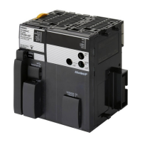
Terminal connection dia-
gram
Laser
OUT0
OUT_COM0
OUT1
OUT_COM1
Connector shell
*3
Power consumption
CK3W-GC1£00: 5 V 0.6 W max., 24 V 1.9 W max.
CK3W-GC2
£00: 5 V 0.6 W max., 24 V 1.0 W max.
Dimensions (height × depth × width) 90(H)/80(D)/63.2(W)
Weight 190 g max.
*1. It is 16 bits for the XY2-100 Interface in general.
*2.
The CK3W-GC£100 Units do not have the OUT1 circuit.
*3.
The CK3W-GC£100 Units do not need the OUT1 wiring.
3-7-2
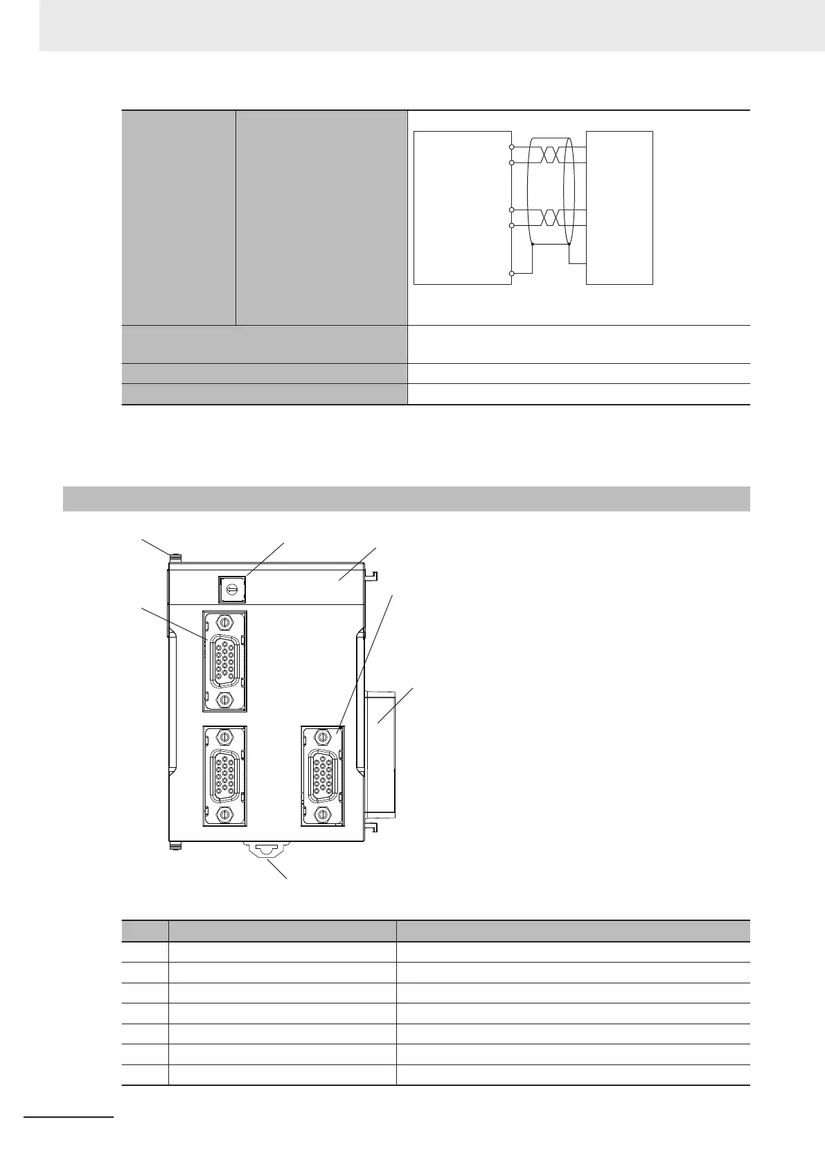
Part Names and Functions
GC2200
ADDRESS
PWR
XY
Z
Laser
(A)
(B)
(C)
(D)
(E)
(F)
(G)
Letter Name Function
A Slider Holds the Units together.
B Address switch Sets the Gate3 Index.
C Power supply status indicator Shows the power supply status.
D Laser connector Connects the laser.
E Unit connector Connector that connects to the Unit.
F DIN Track mounting hook Used to mount the Unit to a DIN Track.
G Galvo Scanner connector Connects the Galvo Scanner.
3 Configuration Units
3-70
CK3M-series Programmable Multi-Axis Controller User's Manual Hardware (O036)
 Loading...