Connect the Unit with the smallest address value to the CPU Rack because, by default, it is the supply
source of clock signals.
You may specify the Unit with a desired address as the clock supply source by setting the register.
If the Unit that serves as the clock supply source is connected to the Expansion Rack, an error occurs
because the CPU Unit cannot recognize clock signals.
If this error occurs, the Sys.Status register Sys.NoClocks becomes
1.
3-7-5
Terminal Arrangement
For the connector arrangement of the Galvo Scanner connector and the laser connector, refer to
5-7-1 Galvo Scanner Connector W
iring on page
5-46 and 5-7-2 Laser Connector Wiring on page
5-48.
3-7-6
XY2-100 Interface
The XY2-100 Interface establishes communications for connecting the Galvo Scanner and the Con-
troller
.
This section describes the functions of the XY2-100 Interface.
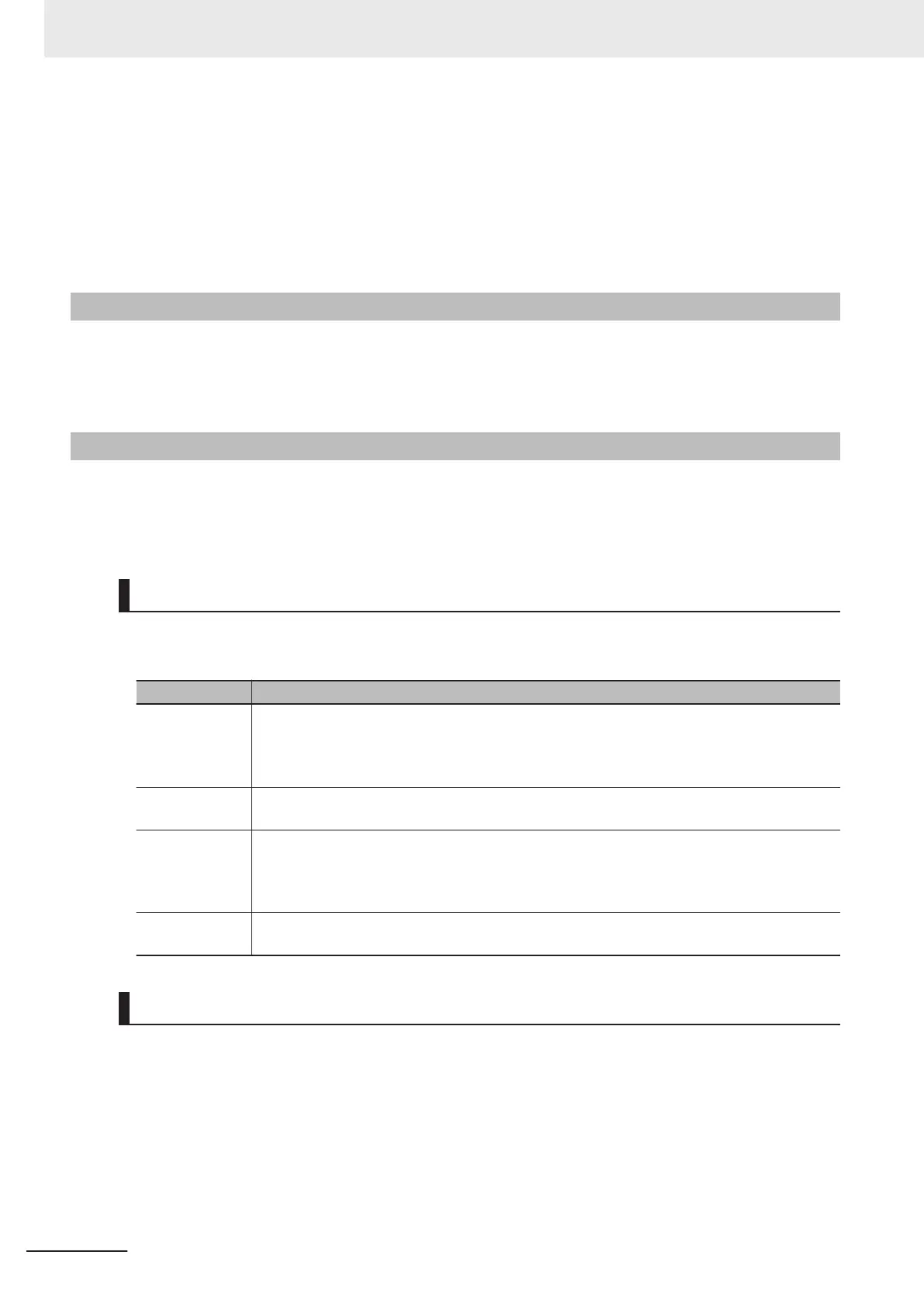
Signal Descriptions
The XY2-100 Interface carries the XY-axis and the Z-axis signals that move the Galvo Scanner re-
spectively in the vertical and horizontal directions and in the height direction.
Name Function
XY-CLOCK/ Z-
CLOCK
A clock signal for communications, and data is sent or received in synchronization with this
clock.
The frequency of this clock is 2 MHz, at which it is sent continuously.
Since a single data is sent or received at 20-clock intervals, data is refreshed every 10 µs.
XY
-SYNC/ Z-
SYNC
A signal for frame synchronization.
CHX/ CHY/
CHZ
Command position data to be sent to the Galvo Scanner.
You can use the setting to select 16-bit, 18-bit, or 20-bit data length.
When the setting is 16 bits or 18 bits, add parity bits to frames. You can change the setting to
choose even or odd parity
.
XY-STATUS/ Z-
STA
TUS
From the Galvo Scanner, 16-bit status data and parity are sent to the CK3W-GC Unit.
You need to use a user program to determine whether the parity is correct.
Data Format of Command Position
A command position is 24-bit data.
To set the command position, use Gate3[i].Chan[j].DAC[0] [31:08].
Y
ou can select a data format of the command position by setting ModeSel (Gate3[i].SerialEncCtrl
[14:15]).
The data ranges from -2
23
to 2
23
.
Data to be sent to the Galvo Scanner is limited to the command position (integer part).
The command position (fractional part) is used to improve the accuracy of linear interpolation.
3 Configuration Units
3-72
CK3M-series Programmable Multi-Axis Controller User's Manual Hardware (O036)
 Loading...