A Appendices
A - 28
E5@C-T Digital Temperature Controllers User’s Manual (H185)
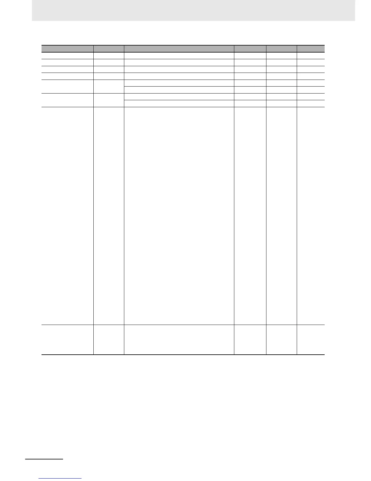
HS Alarm Use hsu OFF, ON off, on ON None
HS Alarm Latch hsl OFF, ON off, on OFF None
HS Alarm Hysteresis hsh 0.1 to 50.0 0.1 A
LBA Detection Time lba 0 to 9999 (0: LBA function disabled) 0 Second
LBA Level lbal Temperature input: 0.1 to 999.9 8.0 °C or °F
Analog input: 0.01 to 99.99 10.00 %FS
LBA Band lbab Temperature input: 0.0 to 999.9 3.0 °C or °F
Analog input: 0.00 to 99.99 0.20 %FS
Control Output 1
Assignment
out1
Relay Output or Voltage Output (for Driving SSR)
*2
ONone
NONE: No assignment none
O: Control output (heating) o
C-O: Control output (cooling) c-o
ALM1: Alarm 1 alm1
ALM2: Alarm 2 alm2
ALM3: Alarm 3 alm3
ALM4: Alarm 4 alm4
HA: Heater alarm (HB + HS) ha
HB: Heater burnout alarm (HB) hb
HS: Heater short alarm (HS) hs
S.ERR: Input error s.err
P.END: Program End output p.end
STG: Stage output stg
RUN: RUN output run
TS1: Time signal 1 output ts1
TS2: Time signal 2 output ts2
ALM: Integrated alarm alm
WR1: Work bit 1
*3
wr1
WR2: Work bit 2
*3
wr2
WR3: Work bit 3
*3
wr3
WR4: Work bit 4
*3
wr4
WR5: Work bit 5
*3
wr5
WR6: Work bit 6
*3
wr6
WR7: Work bit 7
*3
wr7
WR8: Work bit 8
*3
wr8
For Linear Current Output
*2
NONE: Not assigned. none
O: Control output (heating) o
C-O: Control output (cooling) c-o
Control Output 2
Assignment
out2 Same as the Control Output 1 Assignment
parameter.
Same as the
Control
Output 1
Assignment
parameter.
NONE None
Parameters Characters Setting (monitor) value Display Default Unit

 Loading...