No.20S046-00
15/62
FS-C4KU7DGES-F / FS-C4KU7DGES-M42 / FS-C2KU7DGES-F / FS-C2KU7DGES-M42 / FS-C2KU7DGES-C
Product Specifications and Use’s Guide
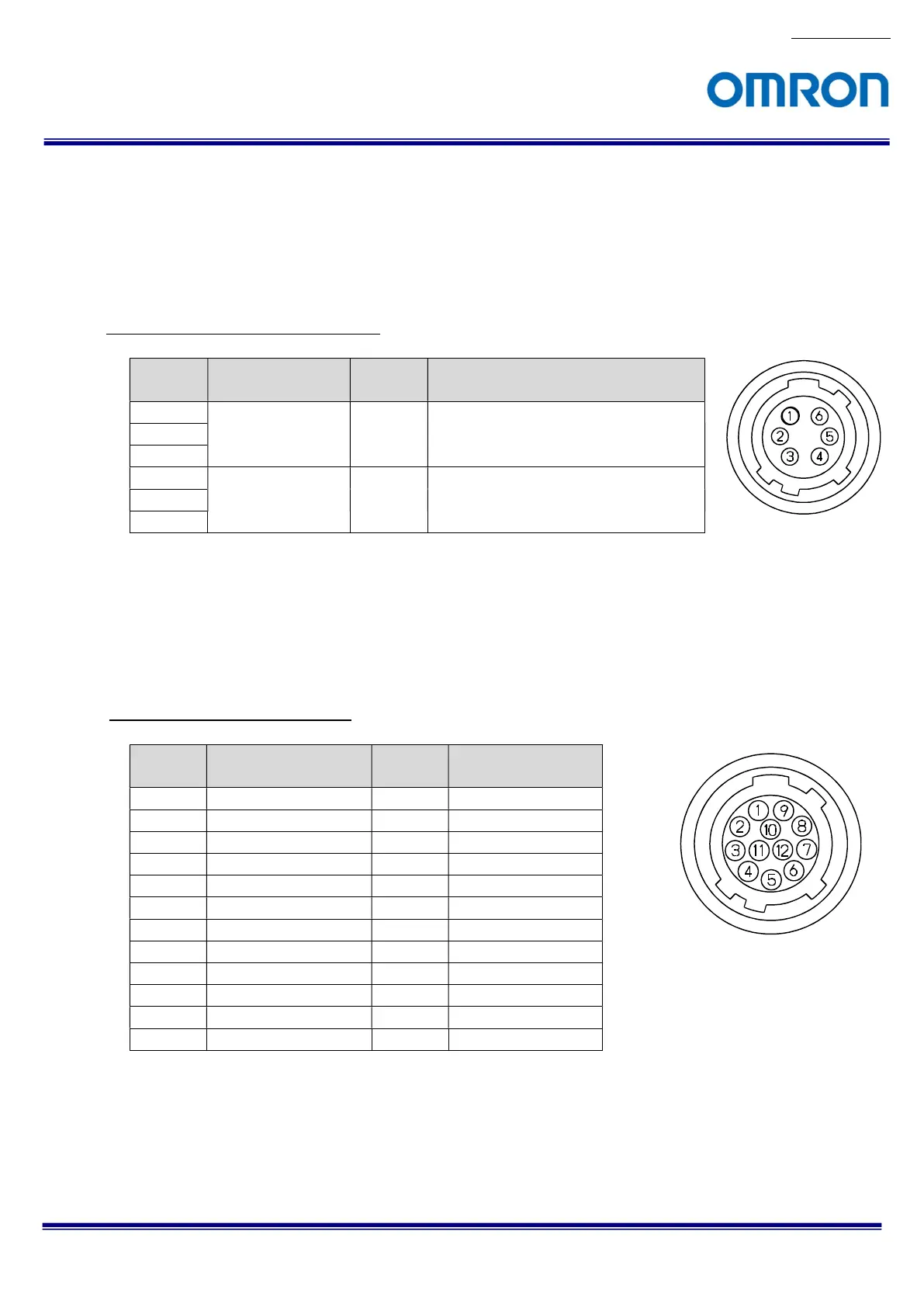
6.2 Power supply connector
HR10A-7R-6PB (Hirose) or equivalent connector x 1
This connector is for power supply only.
Please use the control signal control for control signals.
Please use HR10A-7P-6S (Hirose) or equivalent connector for connecting cable.
Power supply connector pin assignment
Pin No.
Signal Name IN /
OUT
Voltage
1 POWER IN IN +10.8 to +26.4 Vdc
2
3
4 GND IN 0 V
5
6
6.3 IO signal connector
HR10A-10R-12PB (Hirose) or equivalent connector x 1
This connector is for control input and output signals
Please use HR10A-10P-2S (Hirose) or equivalent connector for connecting cable.
IO signal connector pin assignment
Pin No.
Signal Name
IN /
OUT
Voltage
1 INPUT 1- (Line0) IN TTL / RS-422
2 INPUT 1+ (Line0) IN TTL / RS-422
3 INPUT 2- (Line1) IN TTL / RS-422
4 INPUT 2+ (Line1) IN TTL / RS-422
5 GND IN 0 V
6 OUTPUT 1- (Line3) OUT TTL / RS-422
7 OUTPUT 1+ (Line3)
OUT TTL / RS-422
8 INPUT 3- (Line2) IN TTL / RS-422
9 INPUT 3+ (Line2) IN TTL / RS-422
10 POWER IN +10.8 to +26.4 Vdc
11 OUTPUT 2- (Line4) OUT TTL / RS-422
12 OUTPUT 2+ (Line4)
OUT TTL / RS-422
 Loading...


