No.20S046-00
19/62
FS-C4KU7DGES-F / FS-C4KU7DGES-M42 / FS-C2KU7DGES-F / FS-C2KU7DGES-M42 / FS-C2KU7DGES-C
Product Specifications and Use’s Guide
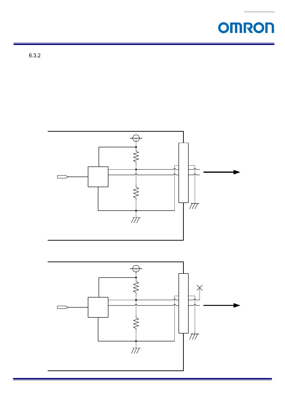
Output Signal Circuit
The signal can be output from below two IO pin on 12pin connector:
Line3 (Pin5: Output0-, Pin6: Output0+)
Line4 (Pin11: Output1-, Pin12: Output1+)
* Output signal circuit for Line0, Line1 and Line3 is same circuit.
RS-422 signal or TTL signal can be input to these IO pin, but It is necessary to change “LineFormat” for IO pin.
The output signal can be selectable at “LineSource” for IO pin.
Please refers “Digital IO Control” section for more details.
Output RS-422 signal
10kΩ
8.2kΩ
+3.3V
1
2
3
4
5
6
7
8
9
10
11
12
LTC
2854
From Internal Circuit
Camera Internal
12Pin Connector
Output0-
Output0+
RS-422
Output Signal
Output TTL signal
10kΩ
8.2kΩ
+3.3V
1
2
3
4
5
6
7
8
9
10
11
12
LTC
2854
From Internal Circuit
Camera Internal
12Pin Connector
Output0-
Output0+
TTL
Output Signal
Not Connected
 Loading...


