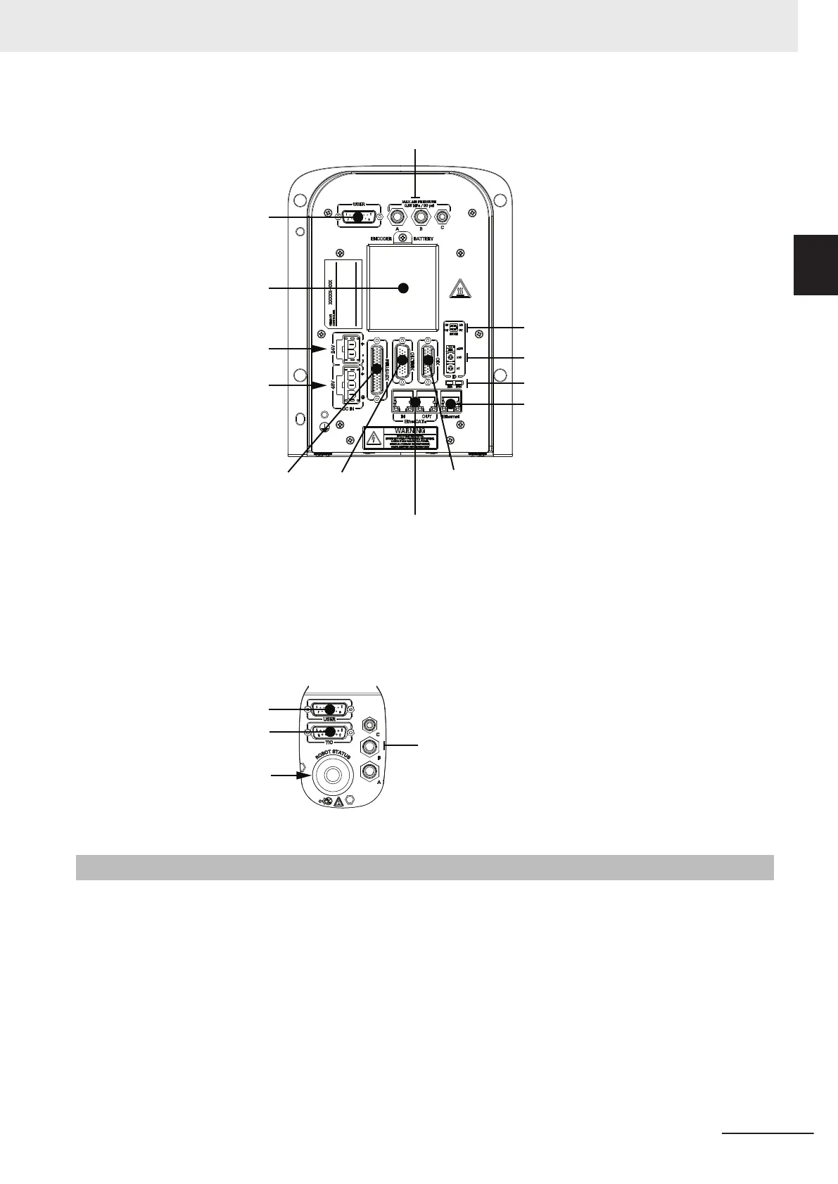
Control Power
Connector
High Power
Connector
XSYSTEM
Connector
XBELTIO
Connector
Reserved
for future
use
XIO
Connector
Ethernet Interface Port
Reserved for future use
Reserved for future use
Mode Switches
Pneumatic Pass-through
Ports
USER Connector
Encoder Backup
Battery Access
Secondary Interface Panel
The Secondary Interface Panel is located on top of the outer link and provides access to the follow-
ing items.
USER Connector
TIO Connector
LED Indicator /
Brake Release
Pneumatic
Pass-through
Ports
1-2-2
Front Panel
The Front Panel is a device that provides remote control and status functions when mounted a safe
distance outside of the robot workspace. The Front Panel provides the following functions.
• Setting the robot mode to Manual or Automatic mode. Refer to 4-2 Robot Control Modes on page
4-3 for more information.
• Indicating the robot High Power and Control Power state.
• Enabling robot High Power. Refer to 4-3-1 Enabling Robot High Power on page 4-5 for more in-
formation.
• Activating an emergency stop and disabling robot High Power.
If Front Panel signals need to be relocated, refer to XFP Wiring Diagram on page 3-24 for internal
circuit details.
1 Overview
1-5
i4L Robots User's Manual (I658)
1-2 Robot Features
1
1-2-2 Front Panel
 Loading...


