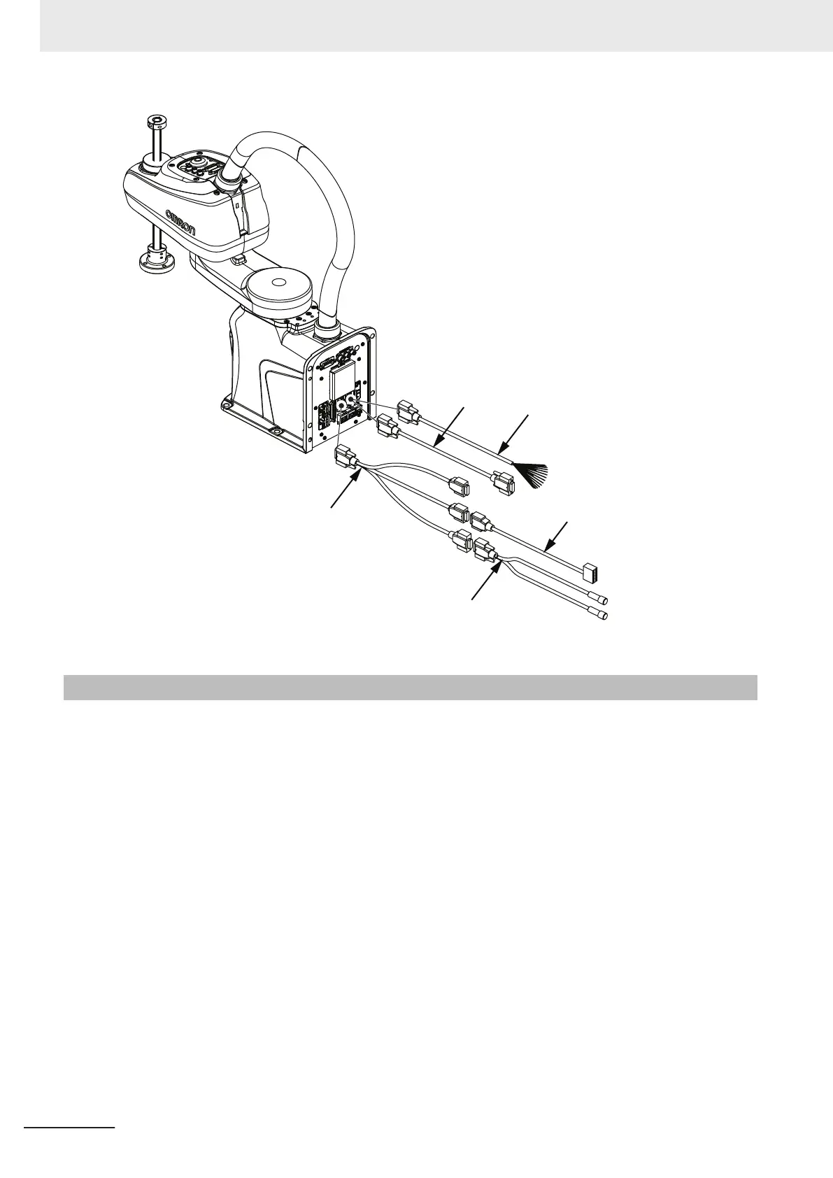
XIO Cable
XBELTIO
Adapter Cable
Belt Encoder
Y-adapter Cable
XIO Breakout
Cable
EXPIO to
IO Blox Cable
3-6-2
System Cable Installation Procedure
The following procedure provides details about system cable installation.
The robot must be mounted before following the steps below. Refer to 3-2 Mounting the Robot on
page 3-3 for more information.
1 Connect the XSYSTEM cable to the Primary Interface Panel XSYSTEM connector and route
the XFP, XUSR, and XMCP connectors to their appropriate locations.
2
Connect external equipment such as the Front Panel and Teach Pendant to the XSYSTEM ca-
ble XFP and XMCP connectors.
Refer to 3-6-1 System Cable Overview on page 3-10 for more information.
3
Connect all user-supplied safety equipment to the XUSR connector on the XSYSTEM cable.
Refer to 3-8 Installing Safety Equipment on page 3-20 for more information.
4 If applicable, connect devices to the XBELTIO connector and the USER connectors.
Refer to Optional Connections on page 3-11 for more information.
5 Connect any digital I/O to the XIO and TIO connectors.
Refer to 3-7 Connecting Digital I/O on page 3-13 for more information.
3 Installation
3-12
i4L Robots User's Manual (I658)
 Loading...


