2-2
Performance Specifications
The following sections provide robot performance specifications.
2-2-1
General Performance Information
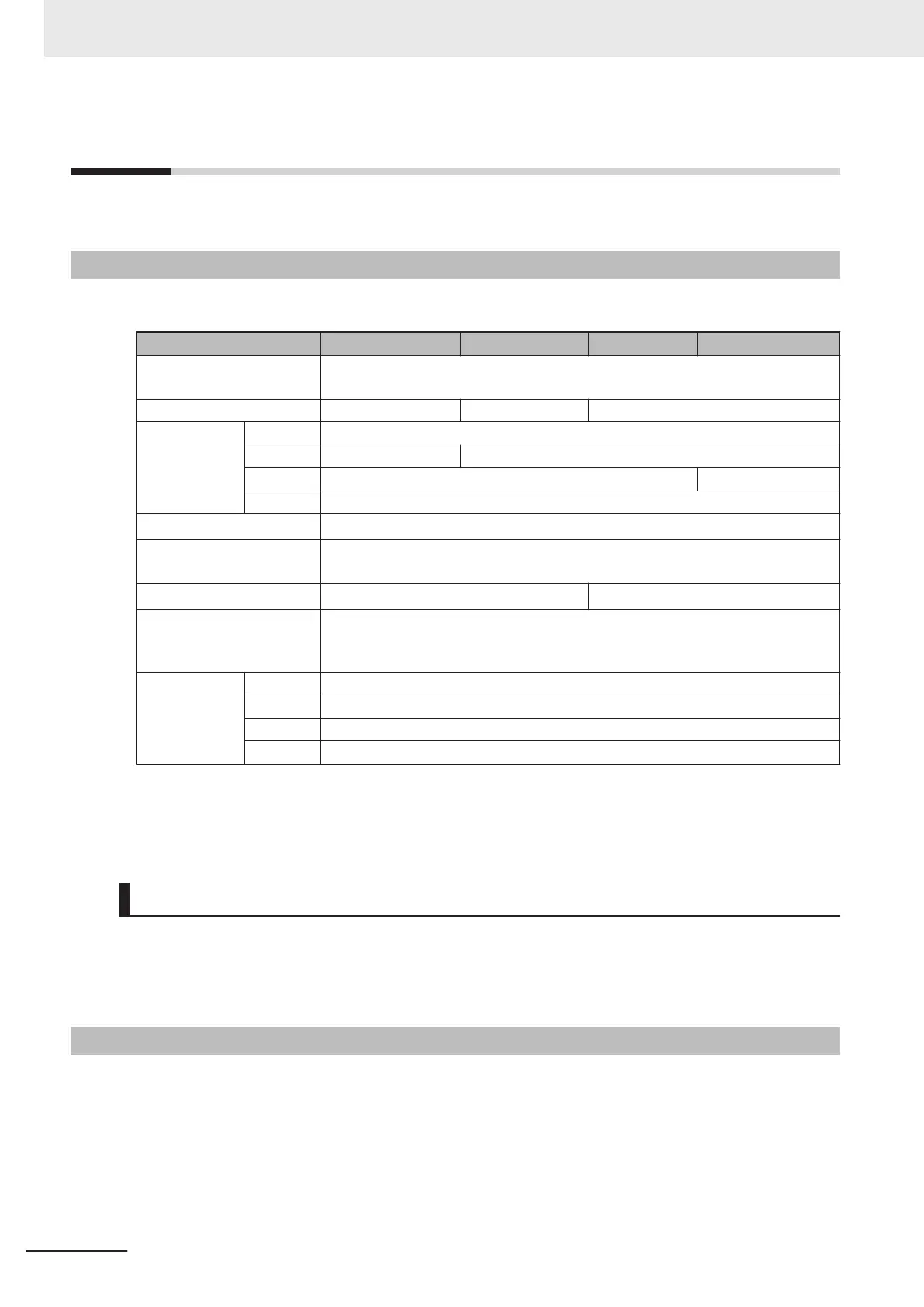
The following table provides general performance information for the robot.
Item i4-350L i4-450L i4-550L i4-550L (350 mm Z)
Payload 2 kg rated
5 kg maximum
Reach 350 mm 450 mm 550 mm
Joint Range Joint 1 ±135°
Joint 2 ±135° ±148°
Joint 3 180 mm 350 mm
Joint 4 ±360°
Joint 4 Moment of Inertia
0.05 kg-m
2
maximum
Downward Push Force
burst with no load
150 N
Cycle Time
*1
0.57 s 0.54 s
Repeatability at 100%
speed
X, Y: 0.01 mm
Joint 3: 0.01 mm
Joint 4: 0.01°
Joint speeds
(maximum)
Joint 1 456 degrees/s
Joint 2 456 degrees/s
Joint 3 800 mm/s
Joint 4 6000 degrees/s
*1. Cycle time is defined as a continuous path with straight-line motion cycle in which the robot tool moves up
25 mm, over 305 mm, down 25 mm, and then back along the same path (not achievable over all paths in
the robot working envelope). Values listed are for sustained motion, no joint 4 rotation, with a 2 kg payload,
at 20° C ambient temperature.
Z-axis Quill Bending Moments
When the robot is operating at high payloads with high acceleration / deceleration, the z-axis quill may
be subject to excessive bending moments. Careful considerations must be made under these condi-
tions. Refer to 4-1 Payload and Speed Considerations on page 4-2 for more information.
2-2-2
Stopping Distances and Times
The following graphs present information required by Clause 7.2 n of ISO 10218-1. This information
should be used to calculate the safe distance needed when designing and installing safeguarding de-
vices.
2 Specifications
2-8
i4L Robots User's Manual (I658)
 Loading...


