Pin Number Designation V+ Signal Number
7 Output 4 36
8 Ground –-
9 Input 1 1033
10 Input 3 1035
11 Ground –-
12 Output 1 33
13 Output 2 34
14 Ground –-
15
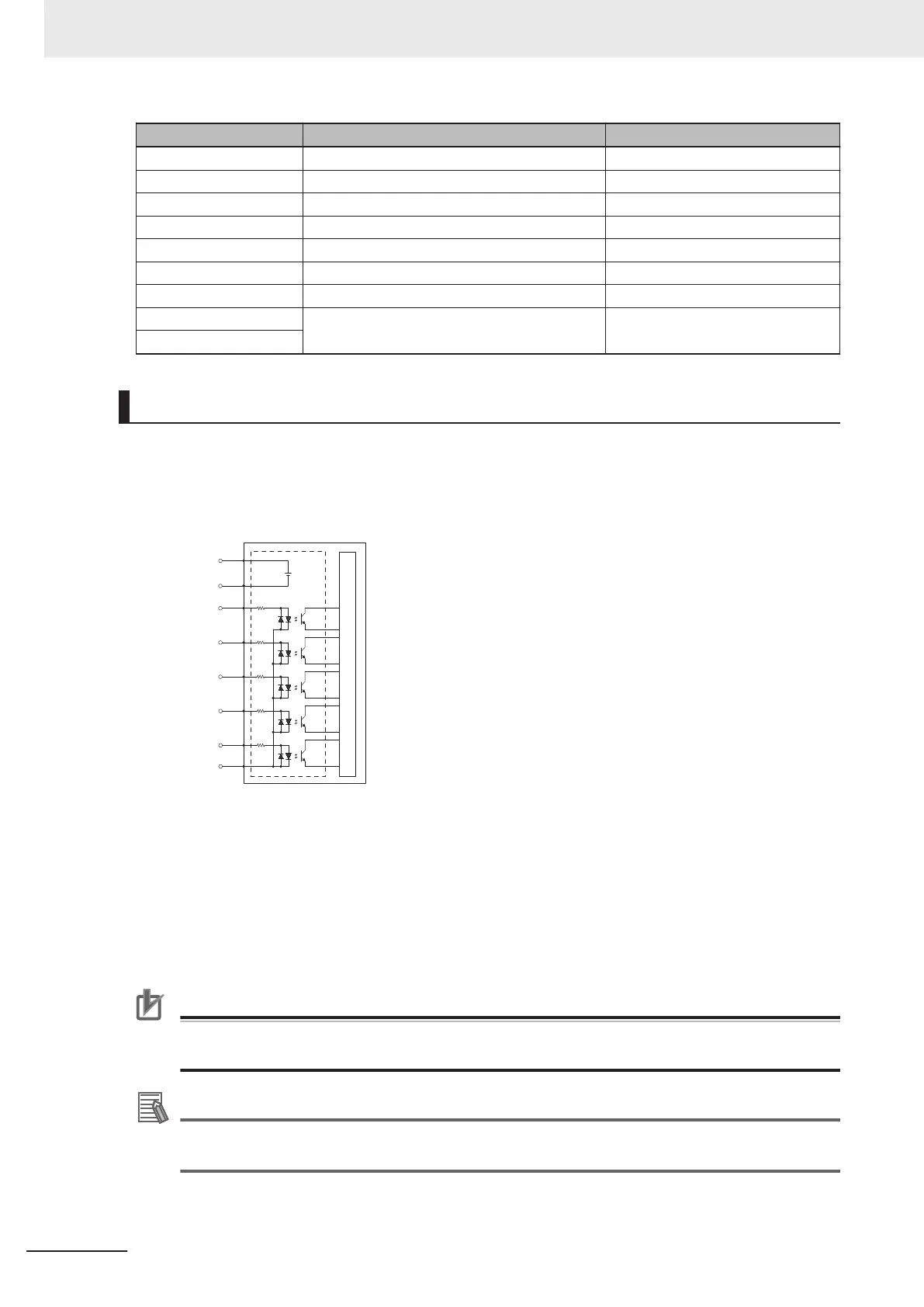
TIO Internal Circuits
Use the following diagram to understand the TIO internal circuits.
TIO Input Signals
The 5 input channels are optically isolated and share a common source / sink line.
Internal Circuits
Input 1
Input 2
Input 3
Input 4
Input 5
Common
24 VDC
Ground
TIO Output Signals
The 4 outputs share a common, sourcing driver integrated circuit. The driver is designed to supply
a load with one side connected to ground. Each channel is capable of switching up to 0.7 A of cur-
rent. This driver has over-temperature protection, shorted load protection, and is current limiting.
The driver draws power from the primary 24 VDC input to the robot through a self-resetting poly-
fuse.
Precautions for Correct Use
Use surge suppression when switching inductive loads such as relays to prevent damage to the
output circuits.
Additional Information
If there is an output short or other over-current situation, the affected output of the driver inte-
grated circuit turns OFF and back ON automatically to reduce the internal temperature.
3 Installation
3-18
i4L Robots User's Manual (I658)
 Loading...


