Chapter 8: LD-250 Rear Facing Laser
Measure in the horizontal plane, from the AMR's center of rotation to the sensor of each laser,
approximately 20 mm from the top. Determine the following measurements:
l
LaserX (front to back)
l
LaserY (left to right)
l
LaserZ (height from floor)
8.2 Ignoring Laser Zones
By default, the sensor scans an arc of 270 degrees. There might be are sections of this arc that
intersect with the AMR or its payload, or with laser protective covers. Therefore, you might
need to set these sections to be ignored by the software. This will make sure that the AMR or
its payload are not detected as obstacles, preventing vehicle motion.
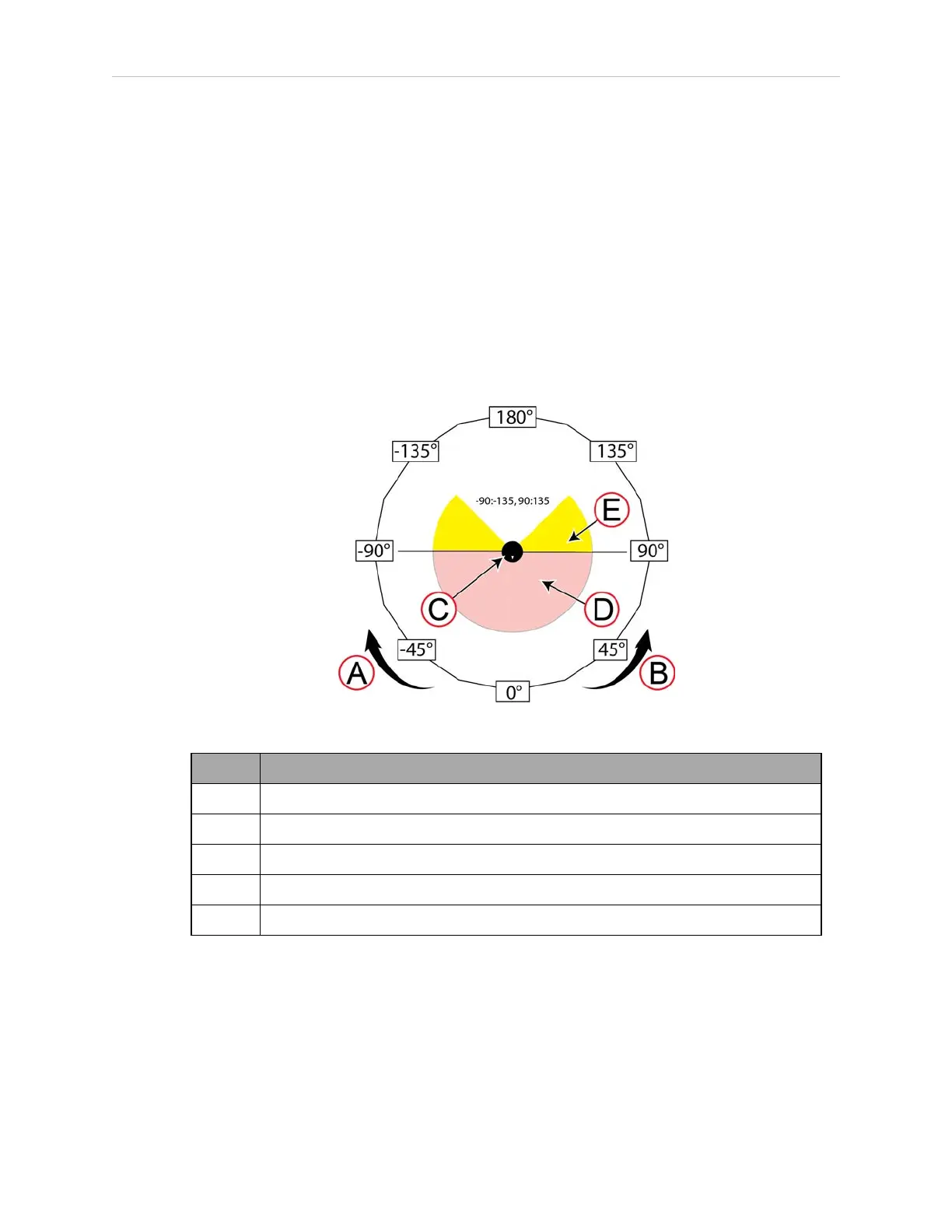
Figure 8-4 Calculating Values for Ignored Laser Zones
Callout
A Negative direction (Clockwise)
B Positive direction (Counterclockwise)
C Laser with a 270 degree scanning plane
D Scanned segment of the 270 degree plane
E Ignored segment of the 270 degree plane
When calculating these values:
l
Degrees of arc relate to the AMR's coordinate system, and not the laser's angular range.
You specify values in the ranges 0° to +180° and 0° to -180° .
l
0 (zero) degrees specifies the AIV's forward direction of travel.
l
The value for an ignored segment cannot span +180 and -180. Thus:
13732-000 Rev J LDPlatform Peripherals Guide 127

 Loading...


