90 LDPlatform Peripherals Guide 13732-000 Rev J
6.1 Tasks
vibration or other movement of the camera makes localization difficult.
l
The payload structure needs four 4.6 mm (0.18 in.) holes and one hole, at least 17 mm
(0.68 in.) in diameter, in the center of that hole pattern. See Hole Pattern of the Camera
Enclosure Base (units are mm (inches)) on page 92.
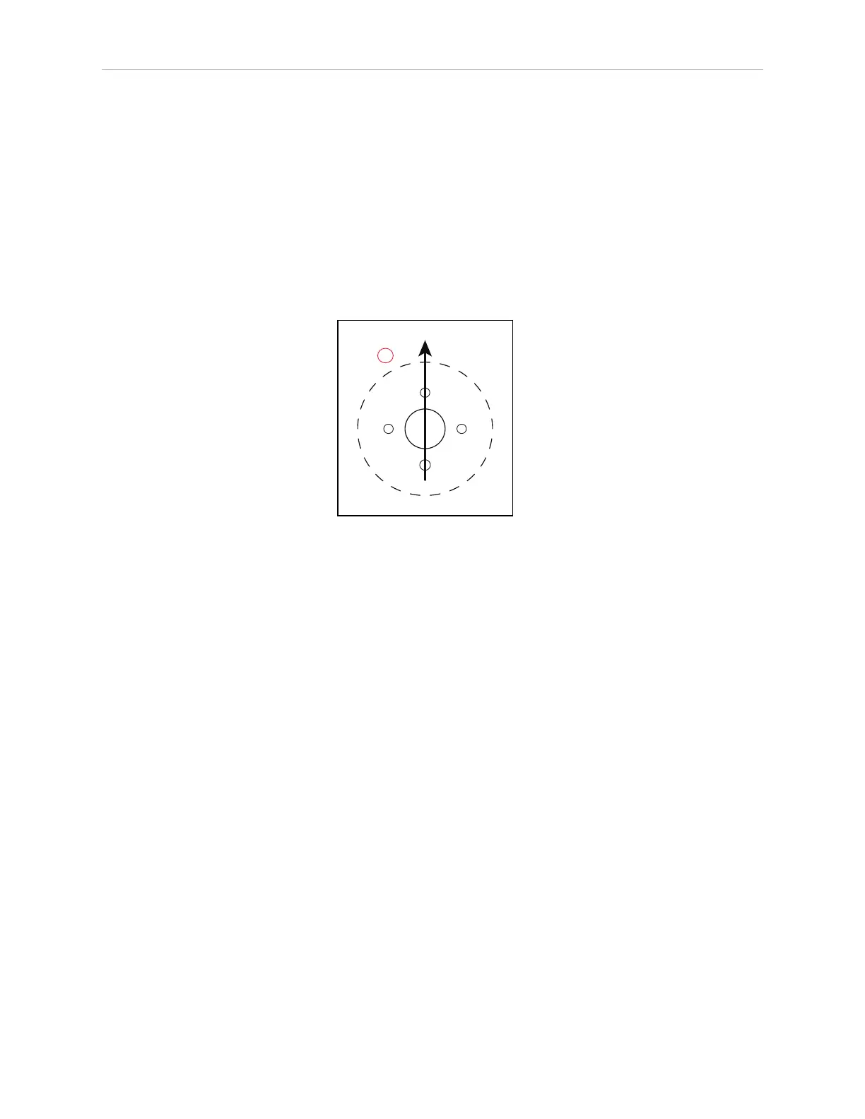
Two of the 4.5 mm holes and the 17 mm hole must line up with the AMR‘s direction of
travel.
NOTE: For localization, the holes (and camera) need to be aligned within
one degree of rotation about the X and Y axes of the platform. See the fol-
lowing figure for hole orientation.
Figure 6-1 (A) Direction of Travel, Hole Pattern
6.1 Tasks
l
Install camera assembly
l
Connect power and data cables between camera and platform core
l
Enable Acuity in MobilePlanner software
l
Load camera calibration file
l
Measure camera position and tilt, enter into MobilePlanner software
l
Create map (will contain both laser and Acuity data)

 Loading...


