Chapter 4: Touchscreen
or a threadlocker, such as Loctite 222. Unthreaded spacers are provided for this method
of mounting.
3.
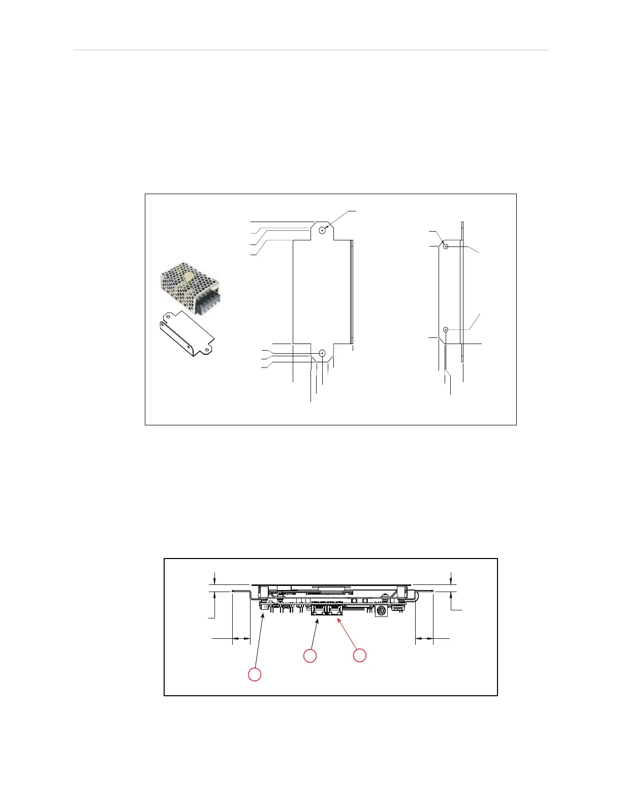
Mount the power supply bracket to existing holes in the top of the platform (payload
bay).
Two holes in the bracket secure the bracket to the platform, two other holes in the
bracket line up with holes in the power supply.
See the following figure.
2 x Ø 5.51 (0.22)
0
2 x 16 (0.63)
2 x 21.01 (0.83)
2 x 26.01 (1.02)
2 x 30.99 (1.22)
2 x 61.47 (1.42)
53.29 (2.1)
0
7.65 (0.3)
2 x 9.65 (0.38)
14.63 (0.58)
83.01 (3.27)
90.65 (3.57)
2 x 92.71 (3.65)
97.64 (3.84)
2 x Ø 3.99 (0.16)
0
2 x 15.29 (0.6)
2 x 16.26 (0.64)
21.29 (0.84)
0
5 (0.197)
11.25
(0.44)
77.75
(3.06)
77.98 (3.07)
Figure 4-4 Power Supply Mounting Bracket Dimensions (units are mm (inches))
Connections
These connections should be made after the mounting procedure is completed.
1.
Connect the 5 VDCpower cord from the power supply to the touchscreen.
2.
Connect an Ethernet cable between the platform core, User LAN port, and the left Eth-
ernet port on the touchscreen. See the following figure.
(0.30)
7.6
(0.30)
7.6
(0.79)
20
(0.79)
20
A
B
C
Figure 4-5 Connections on the Touchscreen (units are mm (inches))
13732-000 Rev J LDPlatform Peripherals Guide 33

 Loading...


