30 LDPlatform Peripherals Guide 13732-000 Rev J
4.1 Installation
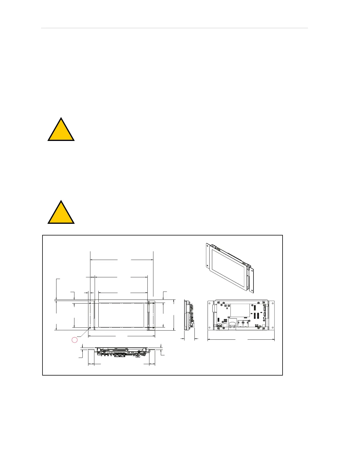
Mounting
If the touchscreen isn’t pre-installed, the placement of the touchscreen on the AMR is up to the
customer. In most cases it will be placed near the top of the payload structure, so an Operator
will have easy access to it. The touchscreen has a bracket, with four mounting holes. The
dimensions are shown in the following figure.
NOTE: The touchscreen electronics need to be protected, so the mounting sur-
face needs a cutout that will accept the touchscreen. Do not surface-mount.
CAUTION: The touchscreen glass is fragile. Take care not to flex the touch-
screen in any way, and to protect the screen from impact.
Mounting Surface Cutout
The mounting surface for the touchscreen needs a cutout large enough for the screen to be
viewed. The four mounting points can either be thru holes, in which case the mounting bolts
will be visible from the outside of the AMR, or you can weld standoffs to the inside of the
mounting surface, to conceal the mounting hardware.
CAUTION: The touchscreen is not centered, horizontally, in the bracket it
comes with. If you are installing the touchscreen yourself, you will need to
account for this, or there will be a small gap at the right side of the screen. See
the following figures.
(3.35)
85
(8.46)
215
(7.07)
179.7
(6.57)
166.9
(4.24)
107.6
(4.06)
103
(3.38)
85.9
(0.43)
10.8
(0.63)
16
(0.24)
6
(8.94)
227
4x Ø
(0.18)
4.5
(0.52)
13.2
(0.16)
4.2
(0.30)
7.6
(0.30)
7.6
(0.79)
20
(0.79)
20
(1.35)
34.4
(8.94)
227
A
Figure 4-1 Mounting Dimensions for the Touchscreen, (A) Through Hole (units are mm (inches))

 Loading...


