5 Designing the Power Supply System
5 - 20
NX-series EtherNet/IP Coupler Unit User’s Manual (W536)
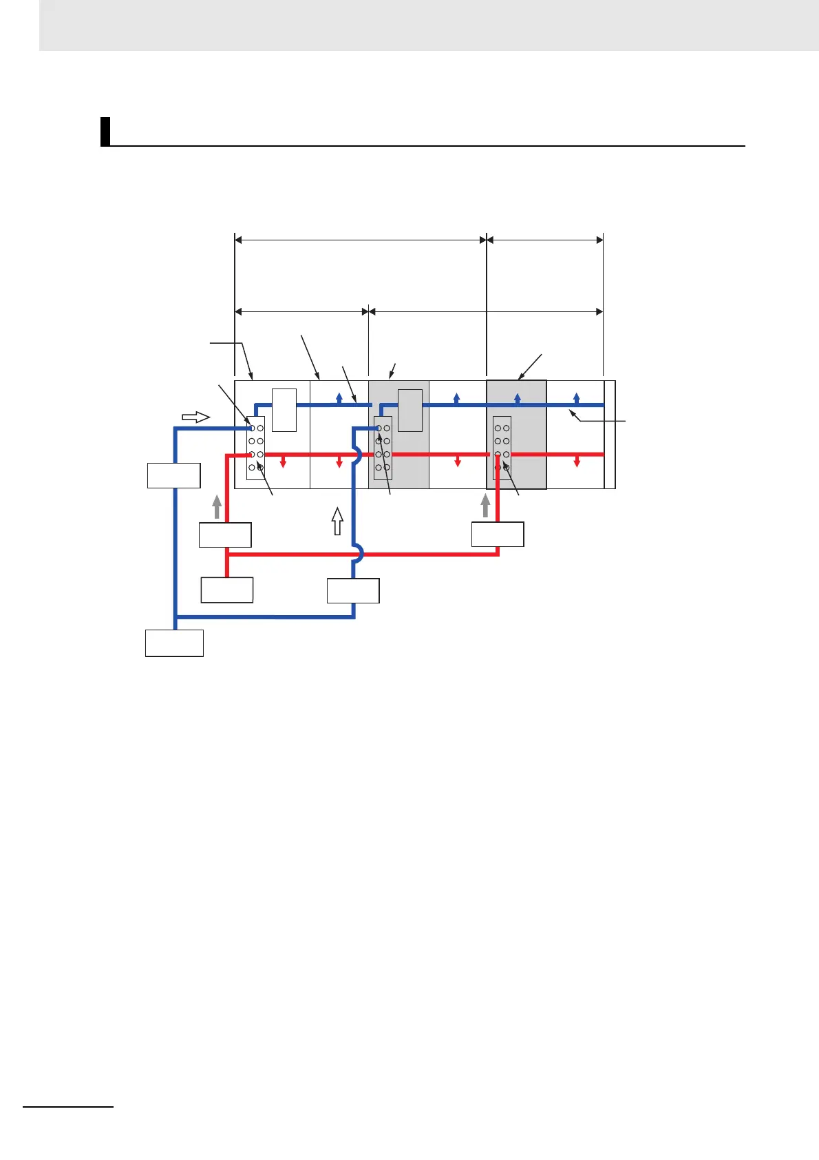
Install protective devices for the Unit power supply and I/O power supply in the locations that are shown
in the following figure.
However, fewer protective devices may be required when the current consumption of each block does
not exceed the rated current. An example of this is provided below.
Installation Locations for Protective Devices
Unit power
supply terminals
EtherNet/IP
Coupler Unit
NX Unit
power supply
NX Unit
power supply
Additional I/O
Power Supply Unit
Additional I/O
Power Supply Unit
I/O power
supply terminals
I/O power
supply terminals
I/O power
supply terminals
I/O power
supply terminals
Unit power
supply terminals
Unit power
supply terminals
Block that is supplied Unit
power from the EtherNet/IP
Coupler Unit
Block that is supplied I/O power from the EtherNet/IP
Coupler Unit
Block that is supplied Unit
power from the Additional
NX Unit Power Supply
Unit
Block that is supplied I/O
power from the Additional
I/O Power Supply Unit
I_unit1
I_unit2
I_io1
I_io2
Internal
power
supply
circuit
NX Unit
Additional NX Unit
Power Supply Unit
Additional NX Unit
Power Supply Unit
I/O power
supply
NX Unit
power
supply
NX Unit
power
supply
Unit power
supply
Protective
device
Protective
device
Internal
power
supply
circuit
Protective
device
Protective
device

 Loading...


