6 - 21
6 Installation
NX-series EtherNet/IP Coupler Unit User’s Manual (W536)
6-1 Installing Units
6
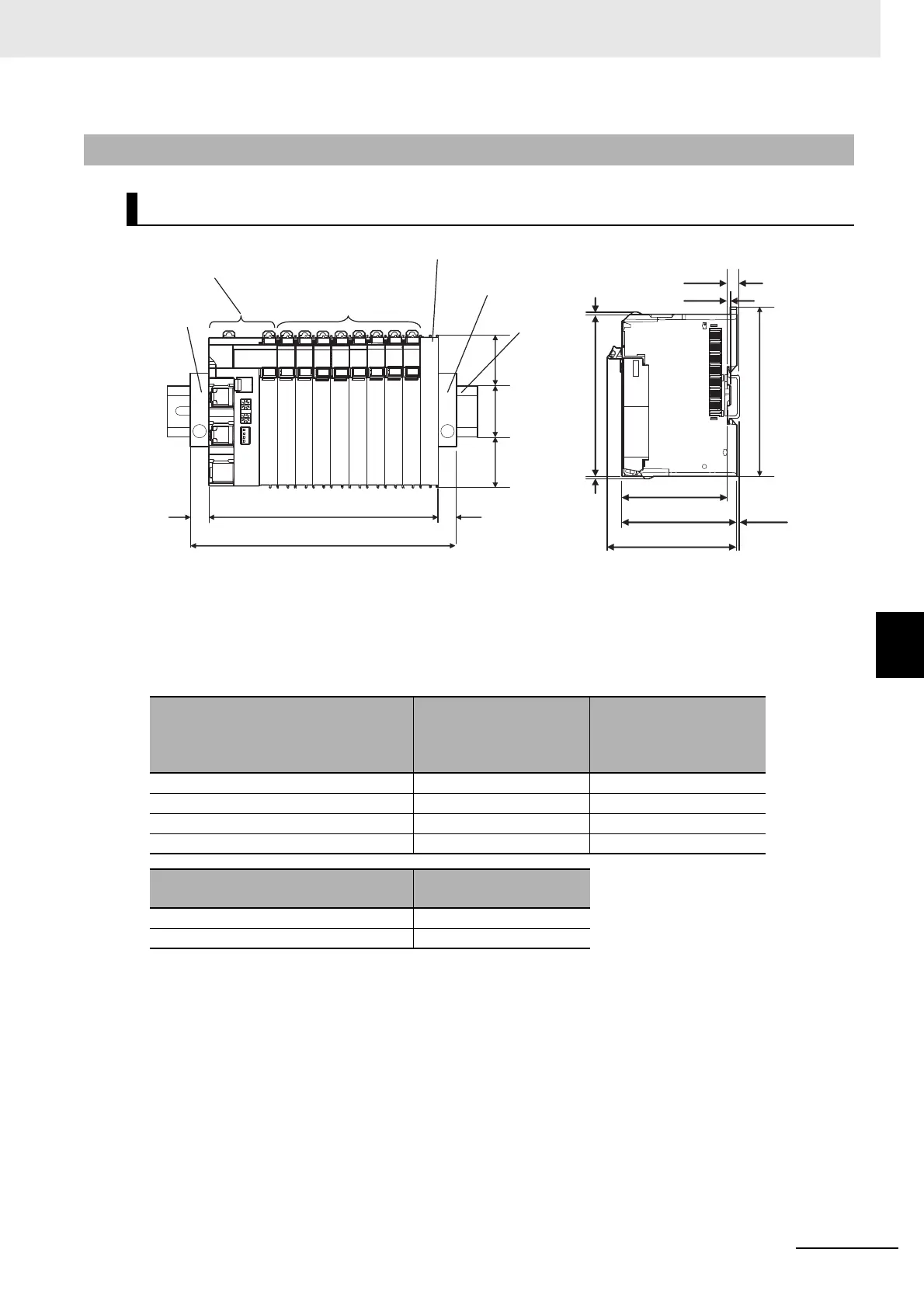
6-1-10 Assembled Appearance and Dimensions
*1. The dimension is 1.35 mm for Communications Coupler Units with lot numbers through December 2014 or for
NX Units with 12-mm widths with lot numbers through December 2014.
W: Width of the EtherNet/IP Slave Terminal
W + (C) + (C): Width of the EtherNet/IP Slave Terminal including the End Plates
6-1-10 Assembled Appearance and Dimensions
Installation Dimensions
DIN Track model
(A)
DIN Track dimension
(B)
Dimension from the
back of the Unit to the
back of the DIN Track
PFP-100N 7.3 mm 1.5 mm
PFP-50N 7.3 mm 1.5 mm
NS 35/7,5 PERF 7.5 mm 1.7 mm
NS 35/15 PERF 15 mm 9.2 mm
End Plate model
(C)
End Plate dimension
PFP-M 10 mm
CLIPFIX 35 9.5 mm
35
34
34
(C)
Coupler Unit
End Plate
NX Units
End Cover
End Plate
DIN Track
(C)
(Unit: mm)
(Unit: mm)
W
W+(C)+(C)
1.5
1.5
(A)
0.55
*1
(B)
71
65.2
100
80
104.5

 Loading...


