Appendices
A - 52
NX-series EtherNet/IP Coupler Unit User’s Manual (W536)
A-5 Application Procedure for the Default
Settings
The NX Units for EtherNet/IP Coupler Units and EtherNet/IP Slave Terminals can be used without con-
figuring the Unit operation settings or NX Unit configuration information with the Support Software. In
that case, the NX Units will operate with their default settings.
This section describes the procedure to configure the Slave Terminal with the default settings. If other
non-default settings are required, Support Software may be required.
Precautions for Correct Use
• NX Unit operation settings are stored in the EtherNet/IP Coupler Unit. If the Unit operation
settings of each Unit and NX Unit configuration information have not been cleared, the mem-
ory of the EtherNet/IP Coupler Unit must be set to the factory state using the clear all mem-
ory function of the Support Software before performing the procedure described in this
section. If all memory is not cleared, stored settings for NX Units that were previously
mounted may be automatically transferred to mounted NX Units. For details on the clear all
memory function of the Sysmac Studio, refer to 11-4 Clearing All Memory on page 11-17.
• The Sysmac Studio is required if you use a Safety Control Unit.
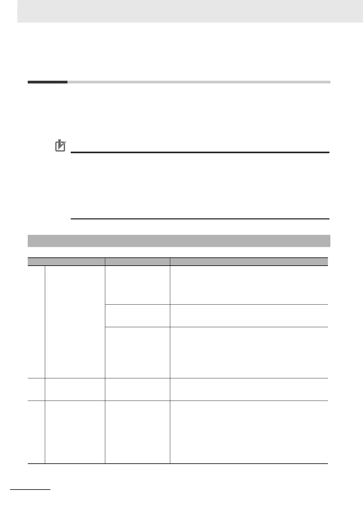
A-5-1 Basic Procedure
Procedure Item Description
1
Making Hardware Set-
tings and Wiring the
Slave Terminal
Switch Settings Set the IP address of the EtherNet/IP Coupler Unit with the
hardware switches. Refer to 4-3 Hardware Switch Settings on
page 4-8.
You can also use the Network Configurator to set the IP
address. Refer to 9-4 Setting IP Address on page 9-31.
Installation Connect the NX Units and End Cover to the EtherNet/IP Cou-
pler Unit and secure the Slave Terminal to a DIN Track to install
it. Refer to 6-1 Installing Units on page 6-2.
Wiring Wire the Slave Terminal. Refer to Section 7 Wiring.
• Connect the communications cables.
• Connect the Unit power supply.
• Connect the I/O power supply.
• Connect the ground wire.
• Connect the external I/O devices.
2
Apply power to the
Slave Terminal
Apply Power During power up and initialization, the EtherNet/IP coupler
automatically detects connected NX Units and applies a default
configuration.
3
Upload EtherNet/IP
Unit Parameters with
Network Configurator
Upload Examine the LED indicators to determine when initialization is
complete. Refer to 12-2 Checking for Errors and Troubleshoot-
ing with the Indicators on page 12-3.
Connect to the EtherNet/IP Coupler Unit with Network Configu-
rator and upload the parameters.
Examine the I/O configuration that was automatically estab-
lished during initialization. Refer to 9-5-4 Determine Tag Sizes
on page 9-40.

 Loading...


