4-43
CHAPTER 4 Adjustment
7 Removing the Robot Covers
To remove the robot cover, follow the procedure below.
1) Prepare the necessary tools.
• Hex wrench set
• Phillips-head screwdriver
2) Turn off the controller.
3) Place a sign indicating the robot is being adjusted, to keep others from
operating the controller switch.
4) Enter the safeguard enclosure.
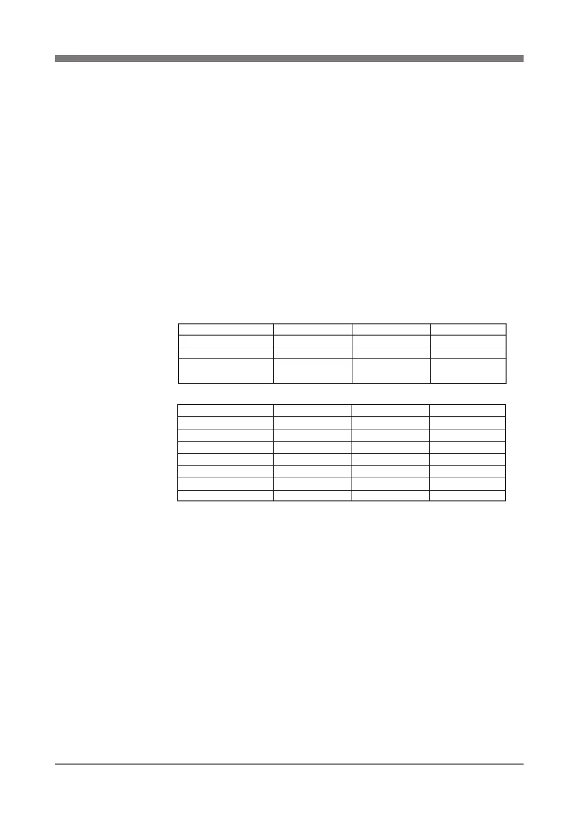
5) Remove the covers while referring to Fig. 4-14 to Fig. 4-15.
Screws used to fasten each cover are listed in Tables 4-4 to 4-5.
Cover name
Base (robot pedestal) rear cover
Base (robot pedestal) front cover
Y-axis arm upper cover
Screw No.
1
2
3
4
5
Screw size
M4x6
M4x6
M3x6
M3x10
M3x16
Qty
4
4
2
2
2
Cover name
Base (robot pedestal) rear cover 1
Base (robot pedestal) rear cover 2
Base (robot pedestal) front cover
X-axis arm upper cover
X-axis arm under cover
Y-axis arm front cover
Y-axis arm side cover
Screw No.
1
2
3
4
5
6
7
Screw size
M4x6
M4x6
M4x6
M4x6
M4x6
M4x6
M4x6
Qty
8
4
4
2
2
14
10
Table 4-5 R6YXX1200 (See Fig. 4-15)
Table 4-4 R6YXH250, R6YXH350, R6YXH400 (See Fig. 4-14)
 Loading...


