3-41
CHAPTER 3 Installation
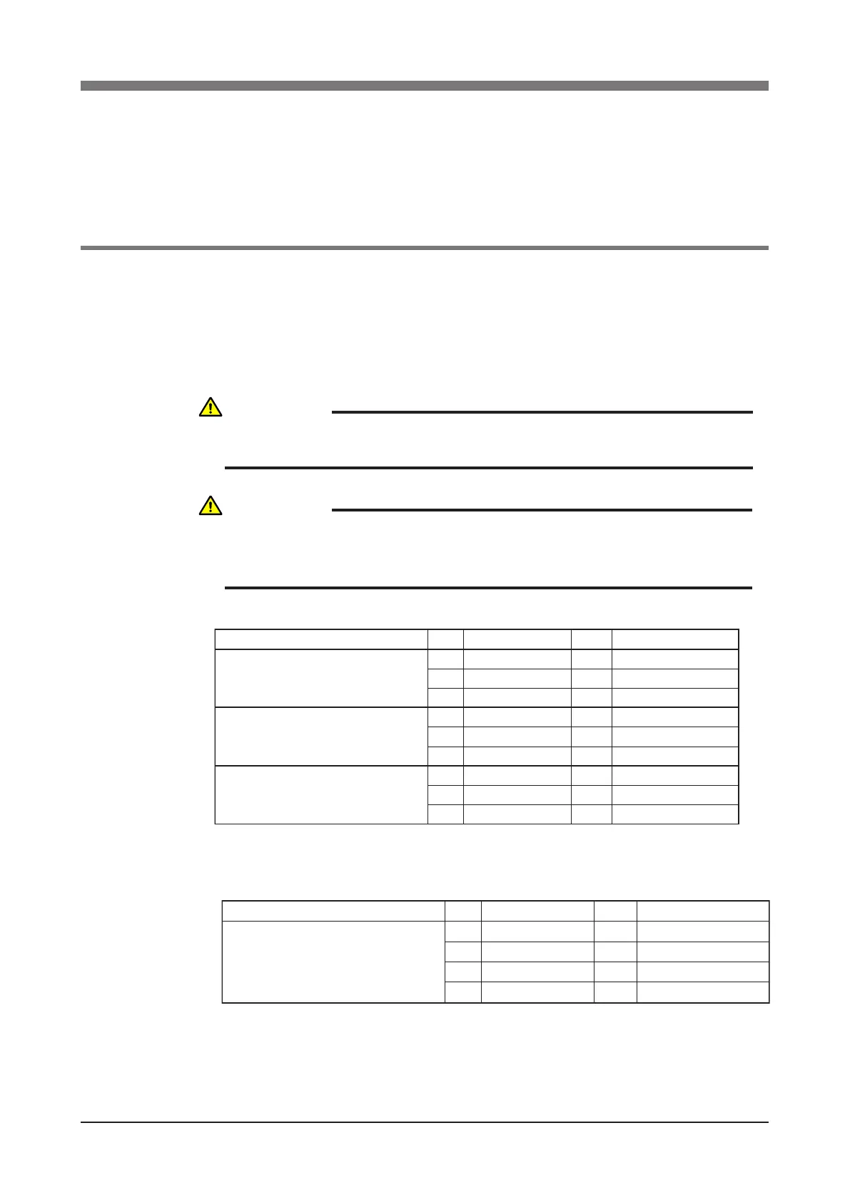
8 Limiting the Movement Range with X-, Y- and Z-
Axis Mechanical Stoppers
(R6YXH250, R6YXH350, R6YXH400)
8-1
Installing the X-, Y- and Z-axis additional mechanical stoppers
The X-, Y- and Z-axis movement ranges can be narrowed as shown in Table 3-6
by ordering and installing additional optional parts listed in Table 3-5.
The mechanical stopper positions may slightly differ depending on machining
precision of the parts and the installation position.
Table 3-5
R6YXH250, R6YXH350, R6YXH400
No.
1
2
3
4
6
5
4
6
5
QtyPart No . Remarks
Additional mechanical stopper parts in
Y-axis minus direction
Additional mechanical stopper parts in
Y-axis plus direction
Additional mechanical stopper parts in
either direction of X-axis plus or minus
direction, or in both directions (*1)
1KN3-M2197-001
190112-10J045
Stopper damper
Bolt
1
99712-10600
KN3-M2197-001
90112-10J045
99712-10600
99712-10600
Nut
Stopper damper
Bolt
Nut
Nut
1
1
1
1
1
1
KN3-M2197-001
90112-10J045
Stopper damper
Bolt
*1: Use one each of these stopper parts to add the stopper in the plus or minus direction or even in both
directions. (When changing the movement range in both directions, move the existing stopper position.)
R6YXH250, R6YXH350, R6YXH400
No.
1
3
2
Qty Part No . Remarks
Additional mechanical stopper parts in
Z-axis plus direction
91312-04012 Bolt
1
2
1
KBE-M1780-000
KN3-M1789-000
Stopper block
Damper
Stopper block
4
1KN3-M183A-100
WARNING
ALWAYS TURN OFF THE CONTROLLER BEFORE CHANGING THE
MOVEMENT RANGE WITH MECHANICAL STOPPERS.
CAUTION
WHEN THE MECHANICAL STOPPERS ARE INSTALLED, THE SOFT
LIMITS MUST BE SET TO A POINT INSIDE THE MECHANICAL STOPPER
POSITIONS.
 Loading...


