3-42
CHAPTER 3 Installation
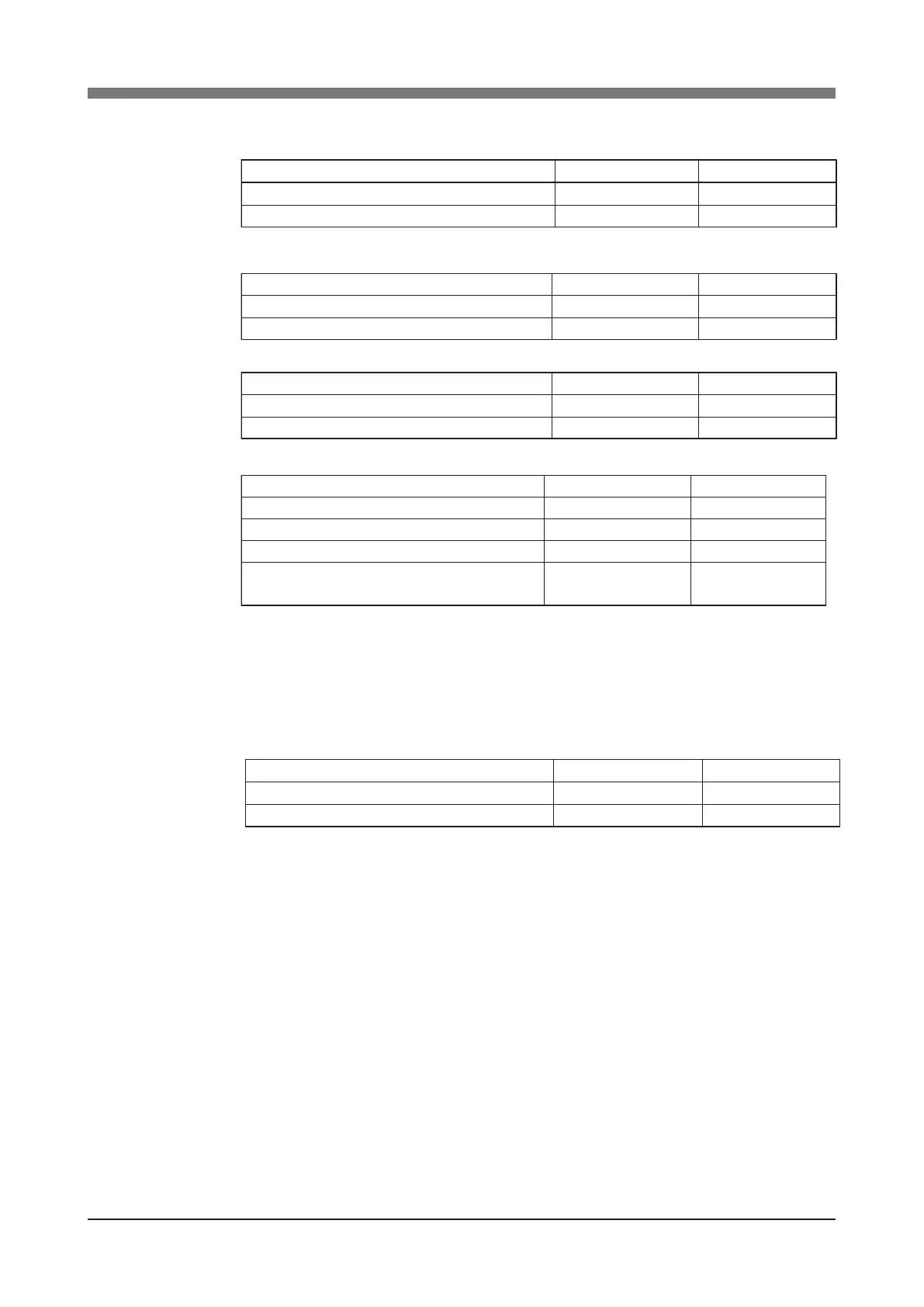
Table 3-6
YK250X(H), YK350X(H), YK400X(H)
Standard stopper Additional stopper
Stopper position in X-axis plus/minus directions
Maximum movement position in X-axis plus/minus
132˚
115˚
105˚
102˚
R6YXH250, R6YXH350, R6YXH400
R6YXH250, R6YXH350
Standard stopper Additional stopper
Stopper position in Y-axis plus/minus directions
Maximum movement position in Y-axis plus/minus directions
142˚
140˚
88˚
85˚
R6YXH400
Standard stopper Additional stopper
Stopper position in Y-axis plus/minus directions
Maximum movement position in Y-axis plus/minus directions
154˚
140˚
88˚
85˚
R6YXH250, R6YXH350, R6YXH400
Standard stopper Additional stopper
Stopper position in Z-axis plus direction (*1)
Maximum movement position in Z-axis plus direction (*1)
Stopper position in Z-axis minus direction (*1)
Maximum movement position (origin position) in
Z-axis minus direction (*1)
158 mm
150 mm
-5 mm
0 mm
158-L
1
mm
100-L
1
mm
L
2
-5 mm
L
2
mm (*2)
*1: The Z-axis movement range and working envelope indicate the positions when the downward
direction relative to the initial Z-axis origin position is set as the plus direction.
The actual origin position is lowered by L
2
and the movement range and stroke are reduced by L
1
+L
2
.
*2: Depending on the relation to the Z-axis machine reference adjustment, L
2
will be a position at
3 mm intervals, such as approximately 12mm, 15mm, etc.
Soft limits after installing additional stoppers
YK250X(H), YK350X(H), YK400X(H)
Soft limit (pulses) Working envelope
X-axis working envelope in plus direction
X-axis working envelope in minus direction
232107
-232107
102°
-102°
R6YXH250, R6YXH350, R6YXH400
 Loading...


