3-51
CHAPTER 3 Installation
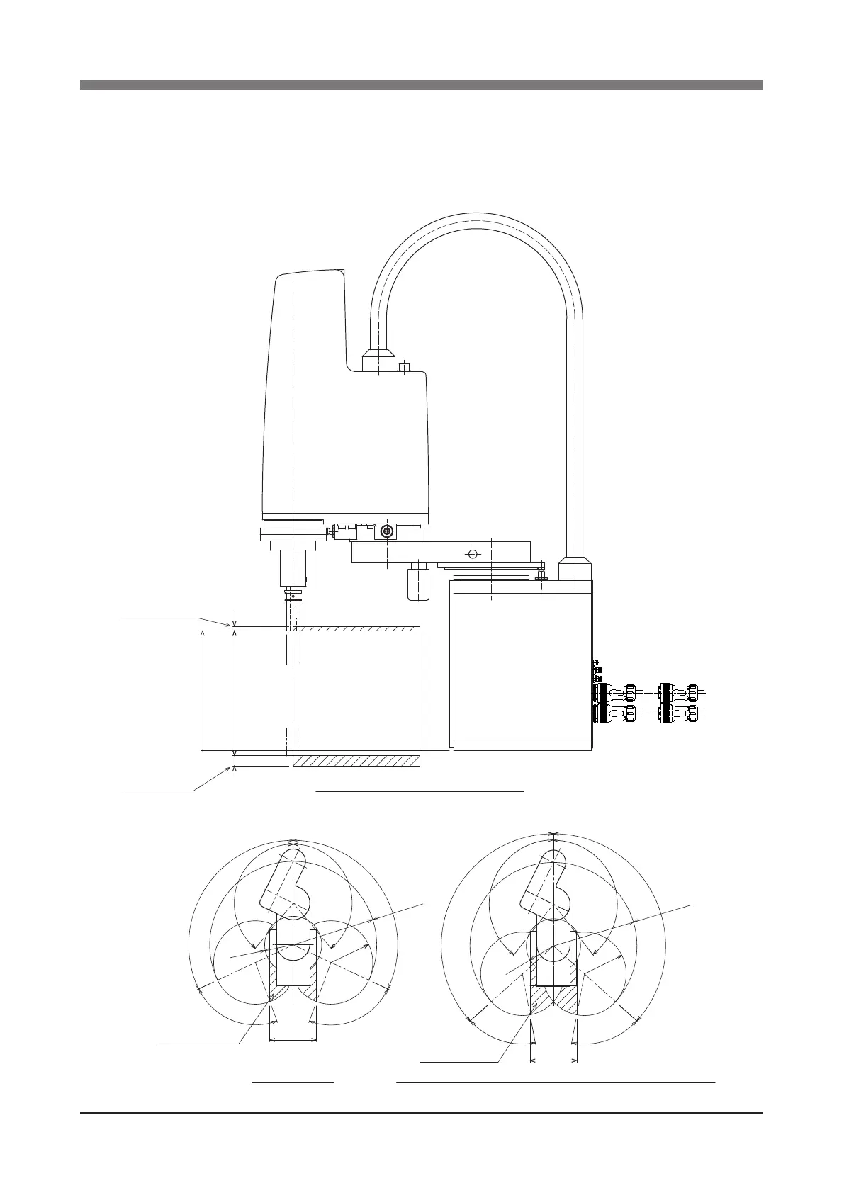
9 Working Envelope and Mechanical Stopper
Positions for Maximum Working Envelope
Working envelope of each robot and mechanical stopper positions for the maxi-
mum working envelope are shown in Fig. 3-47 to Fig. 3-50.
5
150
0
12
140º
115º
R86
R250
R125
140º
115º
85º
140
85º
142º
132º
R250
R81
R125
142º
132º
59º
140
59º
R6YXH250 (Z-axis mechanical stopper position)
Working envelope
Manipulator
interference area
X and Y-axis mechanical stopper positions (maximum working envelope)
Manipulator
interference area
144.52
Z-axis upper end
mechanical stopper
position
Z-axis lower end
mechanical stopper
position
Fig. 3-47 R6YXH250
 Loading...


