3-50
CHAPTER 3 Installation
15) Reattach the Y-axis arm cover.
8-4 Overrun amounts during impacts with X, Y and Z-axis addi-
tional mechanical stoppers
A urethane damper is installed to absorb the shock when an impact occurs
with the mechanical stopper, so a certain amount of overrun occurs when the
robot strikes the mechanical stopper. Use caution and take overrun into account
since the end effector may interfere with the robot body and peripheral equip-
ment or the robot body may interfere with the peripheral equipment.
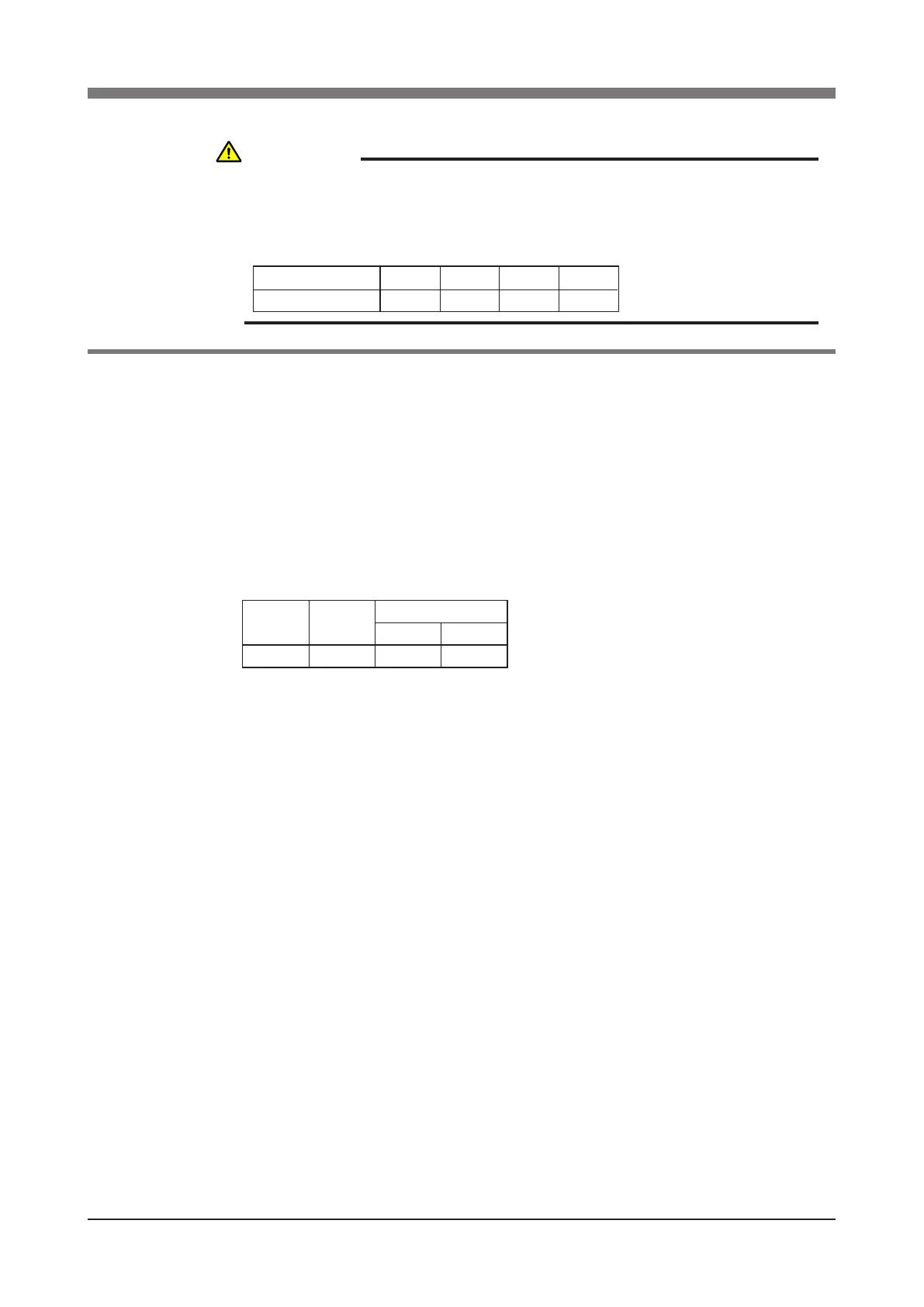
Maximum overrun amounts are listed below (for normal operation, maximum
payload, maximum speed).
5mm
Lower end
2mm
Upper end
Z-axis
16°
Y-axis
10°
X-axis
Note: Here,° (deg.) is the overrun angle at the X-axis and Y-axis joints.
(1) When the robot strikes the X-axis or Y-axis mechanical stopper or another
object, or when the R-axis collides with an object, speed reduction gears
are locked while being meshed if the collision impact is large. If this hap-
pens, please contact our sales ofce or dealer.
(2) If the X-axis, Y-axis or Z-axis mechanical stopper is deformed or damaged
by impacts, please contact our sales ofce or dealer. Using the deformed or
damaged mechanical stopper is dangerous, so it must be replaced.
(3) After the robot strikes the Z-axis mechanical stopper, the stopper position
may shift, and so check the stopper position. If shifted, move the stopper to
the correct position and refasten it securely by following the assembly pro-
cedure.
WARNING
THE PLUS DIRECTION STOPPER WILL BECOME A LOAD, AND SO THE
Z-AXIS ACCELERATION MUST BE REDUCED AS SHOWN BELOW. IF
NOT REDUCED, THE SERVICE LIFE OF THE Z-AXIS DRIVE UNIT WILL
DECREASE.
Tip load
Z-axis acceleration
85%
3kg
90%
2kg
90%90%
1kg0kg
 Loading...


