3-45
CHAPTER 3 Installation
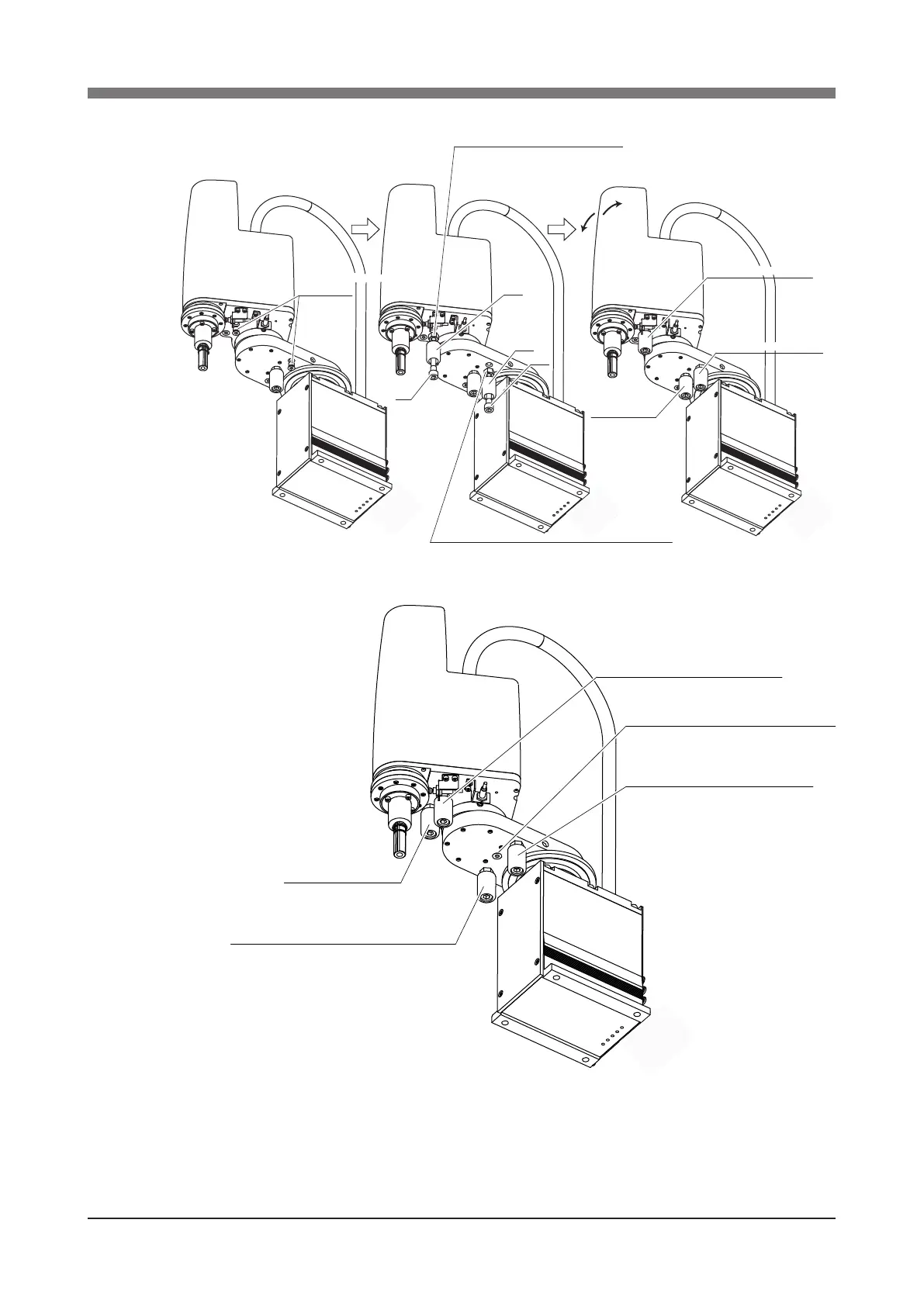
In this case, set the soft limits smaller than the values shown in Table 3-6.
Added X-axis stopper
Added Y-axis stopper
X-axis standard
stopper
1
4
5
3
Tightening torque: 42Nm (425kgf•cm)
Place the damper between the bolt head and nut,
and then tighten the nut to secure the parts to the arm side.
2
6
Tightening torque: 42Nm (425kgf•cm)
Place the damper between the bolt head and nut,
and then tighten the nut to secure the parts to the arm side.
Plus
direction
Minus
direction
Remove the tapped-hole
plug screw.
Stopper added in X-axis plus direction
Screw the plug screw into the tapped hole.
Stopper added in Y-axis plus direction
Stopper added in Y-axis
minus direction
Stopper added in X-axis minus direction
(Move and reinstall the standard stopper here.)
When installing the additional stoppers in both plus and minus directions
Fig. 3-45 XY axes of R6YXH250, R6YXH350, and R6YXH400
 Loading...


