Removing Underfloor Mounted Set
From
RV
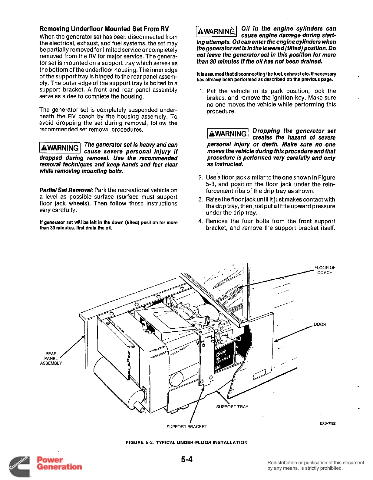
When the generator set has been disconnected from
the electrical, exhaust, and fuel systems. the set may
be partially removed for limited service or completely
removed from the
RV
for major service. The genera-
tor set is mounted on a support tray which serves as
the bottom of the underfloor housing.The inneredge
of the support tray is hinged to the rear panel assem-
bly. The outer edge of the support tray is bolted to a
support bracket.
A
front and rear panel assembly
serve as sides to complete the housing.
The generator set is completely suspended under-
neath the
RV
coach by the housing assembly. To
avoid dropping the set during removal, follow the
recommended set removal procedures.
The generator set
is
heavy and can
!2EBWil
cause severe personal injury
if
dropped during removal. Use fhe recommended
removai techniques and keep hands and feef clear
while removing mounfing
boifs.
Partial Set Removal:
Park the recreational vehicle on
a level as possible surface (surface must support
floor jack wheels). Then follow these instructions
very carefully.
If
generator set will be left in the down (tilted) position
for
more
than
30
minutes, first drain the
oil.
Oil in the engine cylinders can
k&&!@@d
cause engine damage during sfart-
ingattempfs. Oiican enter the engine cyiinders when
the generator set
is
in
the
io
wered (tilted) position. Do
not ieave the generator set
in
this
position for more
than
30
minufes if the
oil
has not been drained.
It is assumed that disconnecting the fuel, exhaustetc.
if
necessary
has already been performed as described on the previous page.
1.
Put the vehicle in its Dark Dosition, lock the
2.
3.
4.
brakes, and remove the’ignition key. Make sure
no one moves the vehicle while performing this
procedure.
Dropping the generator sef
creafes the hazard of severe
personal injury or deafh. Make sure
no
one
moves fhe vehicle during this procedure
and
that
procedure
Is
performed very carefuiiy and only
as
instructed.
Useafloorjacksimilarto theoneshown in Figure
5-3,
and position the floor jack under the rein-
forcement ribs
of
the drip tray as shown.
Raise the floor jack until
it
just makes contact with
the drip tray, then just put a little upward pressure
under the drip tray.
Remove the four bolts from the front support
bracket, and remove the support bracket itself.
SUPPORT
BRACKET
FIGURE
5-2.
TYPICAL
UNDER-FLOOR
INSTALLATION
5-4
EXS-1122
Redistribution or publication of this document
by any means, is strictly prohibited.
Redistribution or publication of this document
by any means, is strictly prohibited.
 Loading...


