.
carbon deposits. Carbon prevents heat dissipation.
Clean metal is a good heat conductor but carbon insu-
lates and retains heat. This increases combustion
chamber temperatures which causes warping and
burning.
Unburned carbon residue gums valve stems and
causes them to stick in the guide. Deposits of hard
carbon with sharp points projecting become white hot
and cause pre-ignition and “pinging”.
ValveSfemSeakAvalvestem seal is used on theintake
valve guides. This seal must be replaced each time the
valve is removed.
Stems
and Guides: Always check valve stems and
guides for wear as shown in Figure 9-6. Use a hole
gauge to measure the valve guide. When clearance
with stem exceeds original clearance by
0.002
inch
(0.05
mm), replaceeithervalveorguideorboth, asmay
be necessary. Always regrind seat to make concentric
with the newly installed guide.
VT-1020
FIGURE
9-6.
VALVE
STEM
AND VALVE GUIDE INSPECTION
Spring:
Check valve springs for cracks, worn ends,
distortion and tension. If spring ends are worn, check
valve spring retainer for wear. Check for spring distor-
tion by placing spring on aflat surface next to asquare.
Measure height of spring and rotate
it
against square
edge
to
measure distortion. Check spring tension at
the installed height for both the valve open and closed
position using an accurate valve spring tester. Replace
any valve spring that is weak, cracked, worn or
distorted.
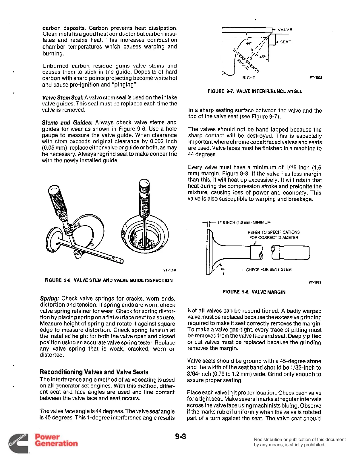
Reconditioning Valves and Valve Seats
The interference angle method of valveseating is used
on all generator set engines. With this method, differ-
ent seat and face angles are used and line contact
between the valve face and seat occurs.
Thevalve faceangle is44
degrees.Theva1veseafangle
is
45 degrees. This l-degree interference angle results
VALVE
+Ad
FIGURE 9-7. VALVE INTERFERENCE ANGLE
in a sharp seating surface between the valve and the
top
of
the valve seat (see Figure
9-7).
The valves should not be hand lapped because the
sharp contact will be destroyed. This is especially
important where chrome cobalt faced valves and seats
are used. Valve faces must be finished in a machine to
44 degrees.
Every valve must have a minimum
of
1/16 inch (1.6
mm) margin, Figure 9-8. If the valve has less margin
than this, it will heat up excessively.
It
will retain that
heat during the compression stroke and preignite the
mixture, causing loss of power and economy. This
valve is also susceptible to warping and breakage.
7
1/16 INCH
(1.6
mm)
MINIMUM
REFER
TO
SPECIFICATIONS
FOR
CORRECT
DIAMETER
VT-1022
FIGURE
9-8.
VALVE MARGIN
Not all valves can be reconditioned.
A
badly warped
valve must be replaced because theexcessive grinding
required to make it seat correctly removes the margin.
To
make a valve gas-tight, every trace of pitting must
be removed from the valve face and seat. Deeply pitted
or cut valves must be replaced because the grinding
removes the margin.
Valve seats should be ground with a 45-degree stone
and the width
of
the seat band should be 1/32-inch
to
3/64-inch
(0.79
to
1.2
mm) wide. Grind onlyenough
to
assure proper seating.
Place each valve in,
it
proper location. Check each valve
fora tight seat. Makeseveral rnarksat regular intervals
across the valve face using machinists bluing. Observe
if
the marks rub
off
uniformly when the valve is rotated
part of a turn against the seat. The valve seat should
9-3
Redistribution or publication of this document
by any means, is strictly prohibited.
Redistribution or publication of this document
by any means, is strictly prohibited.
 Loading...


