Replacement:
After the
old
seat has been removed,
clean carbon or metal burrs from the seat insert
recess. Use a valve seat insert driver and a hammer to
install the inserts.
Insert the pilot of the tool into the valve guide hole in
the cylinder block. Quickly drive in the valve seat
insert
so
that the insert goes evenly to the bottom
of
the recess in the cylinder block. Make certain that the
valve seat insert rests solidly on the bottom of the
recess around its complete circumference (see Fig-
ure
9-1
1).
Thevalveseat must bestaked toassureatightfitand
eliminate the danger of its loosening in the bore.
Refinish valve seat inserts before installing valves.
Insert valve seat staker in the cylinder block valve
guide hole. Rotate thestaking tool until
it
dropsto the
original stake marks. Rotate staking tool another
60
degrees
(1/6
turn). Using a lead hammer, strike the
staking tool asharp blow to wedge the new valve seat
securely in place.
Tappet Adjustment
The engine is equipped with adjustable valve tappets.
Adjust the valve clearance only when engine is at
ambient temperature. Proceed as follows:
1.
Remove all parts necessary to gain access to
valve tappets.
2.
Remove spark
plugs
to make turning the engine
easier.
3.
Place a socket wrench
on
the flywheel capscrew
and rotate the crankshaft in aclockwise direction
until the left intake valve (viewed from flywheel
end) opens and closes. Continue turning the
crankshaft until the
TC
mark on the flywheel is
lined up with theTC mark on thegear cover. This
should place the left piston
(#1)
at the top of its
compression stroke. Verify that the left intake and
exhaust valves are closed and there is no pres-
sure on the valve lifters.
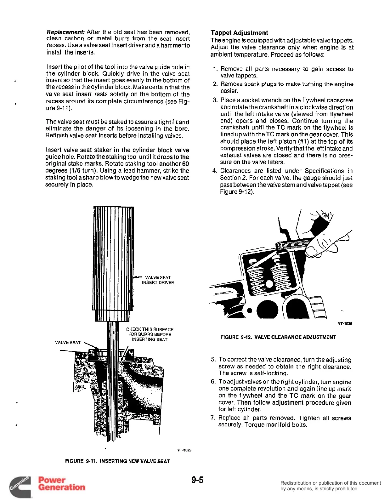
4.
Clearances are listed under Specifications in
Section
2.
For each valve, the gauge should just
pass between the valve stem and valve tappet (see
Figure
9-12).
VT-1026
CHECK
THIS
SURFACE
FOR
BURRS BEFORE
INSERTING
SEAT
FIGURE
9-12.
VALVE CLEARANCE ADJUSTMENT
5.
To correct the valve clearance, turn the adjusting
screw as needed to obtain the right clearance.
The screw is self-locking.
6.
To adjust valves on the right cylinder, turn engine
one complete revolution and again line up mark
on the flywheel and the
TC
mark on the gear
cover. Then follow adjustment procedure given
for left cylinder.
7.
Replace all parts removed. Tighten all screws
securely. Torque manifold bolts.
VT-1025
FIGURE
9-11.
INSERTING NEW VALVE SEAT
9-5
Redistribution or publication of this document
by any means, is strictly prohibited.
Redistribution or publication of this document
by any means, is strictly prohibited.
 Loading...


